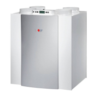
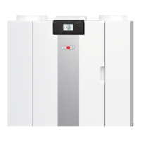
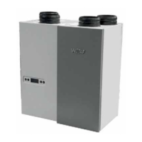
12 Heat Recovery unit CWL-300(B) / CWL-400(B) with option PCB
Parameter U6 must be set on the control panel. U6 shows the
target temperature of the postheater. The setting parameters
are shown in § 4.2.4.
Refer to § 6.5 for connecting the postheater.
Chapter 4 Settings
4.3 Modifying setting parameters
Chapter 1 indicates the connection possibilities offered by the
RSWLRQ SFE :KHQ FRQQHFWLQJ WKH YDULRXV FRPSRQHQWV SDUD-
meters must also be set on the control panel. Setting or mo-
difying parameters is described in § 4.2.1 and 4.2.2.
4.3.1 Switch input incidents
Parameters P1 and P2 must be set on the control panel.
P1 represents the air quantity of the input fan and P2 re-
presents the air quantity of the output
fan. When the switch
contact is made, both fans will run at the preset air quanti-
ties P1 and P2. The setting parameters as shown in § 4.2.4.
4.3.2 Switch input bedroom valve
Parameters P3 and P4 must be set on the control panel. P3
represents the additional air quantity of the input fan and P4
represents the additional air quantity of the output fan. When
the switch contact is made, both fans will run at the air quantity
of the 3-way switch, increased by the preset air quantities P3
and P4. The setting parameters are shown in § 4.2.4.
4.3.3 Programmable make contact 1
Parameters P5, P6 and P7 must be set on the control panel. P5
indicates where make contact 1 must be linked to, P6 and P7
indicate what the air quantity must be for the input and output
IDQUHVSHFWLYHO\7KHVHWWLQJSDUDPHWHUVDVVKRZQLQ
4.3.4 Programmable make contact 2
Parameters P8, P9 and P10 must be set on the control panel. P8
indicates where make contact 2 must be linked to, P9 and P10
indicate what the air quantity must be for the input and output
IDQUHVSHFWLYHO\7KHVHWWLQJSDUDPHWHUVDUHVKRZQLQ
4.3.5 Humidity sensor input
Parameters U7, P11, P12 and P13 must be set on the control
SDQHO 8 LQGLFDWHV KRZ WKH FRQWURO UHVSRQGV WR WKH YROWDJH
RIWKHSURSRUWLRQDOLQSXW3LQGLFDWHVWKHWDUJHWYROWDJH3
LQGLFDWHVWKHPD[LPXPYROWDJHRIWKHGHYLFHFRQQHFWHGWRWKH
input. P13 shows the integration time of the PI controller. The
setting parameters are shown in § 4.2.4.
4.3.6 Input for CO2 sensor
Parameters U7, P14, P15 and P16 must be set on the control
SDQHO8LQGLFDWHVKRZWKHFRQWUROUHVSRQGVWRWKHYROWDJHRI
WKH SURSRUWLRQDO LQSXW 3 LQGLFDWHV WKH WDUJHW YROWDJH 3
LQGLFDWHVWKHPD[LPXPYROWDJHRIWKHGHYLFHFRQQHFWHGWRWKH
input. P16 shows the integration time of the PI controller. The
setting parameters are shown in § 4.2.4.
4.3.7 Control postheater up to 1000 W
4.3.8 Control preheater up to 1000 W
Parameter U17 must be set on the control panel. P17 indicates
whether or not a preheater is present. The setting parameters
are shown in § 4.2.4.
Refer to § 6.6 for connecting the preheater.