16 Heat Recovery unit CWL-300(B) / CWL-400(B) with option PCB
Chapter 6 Electric diagrams
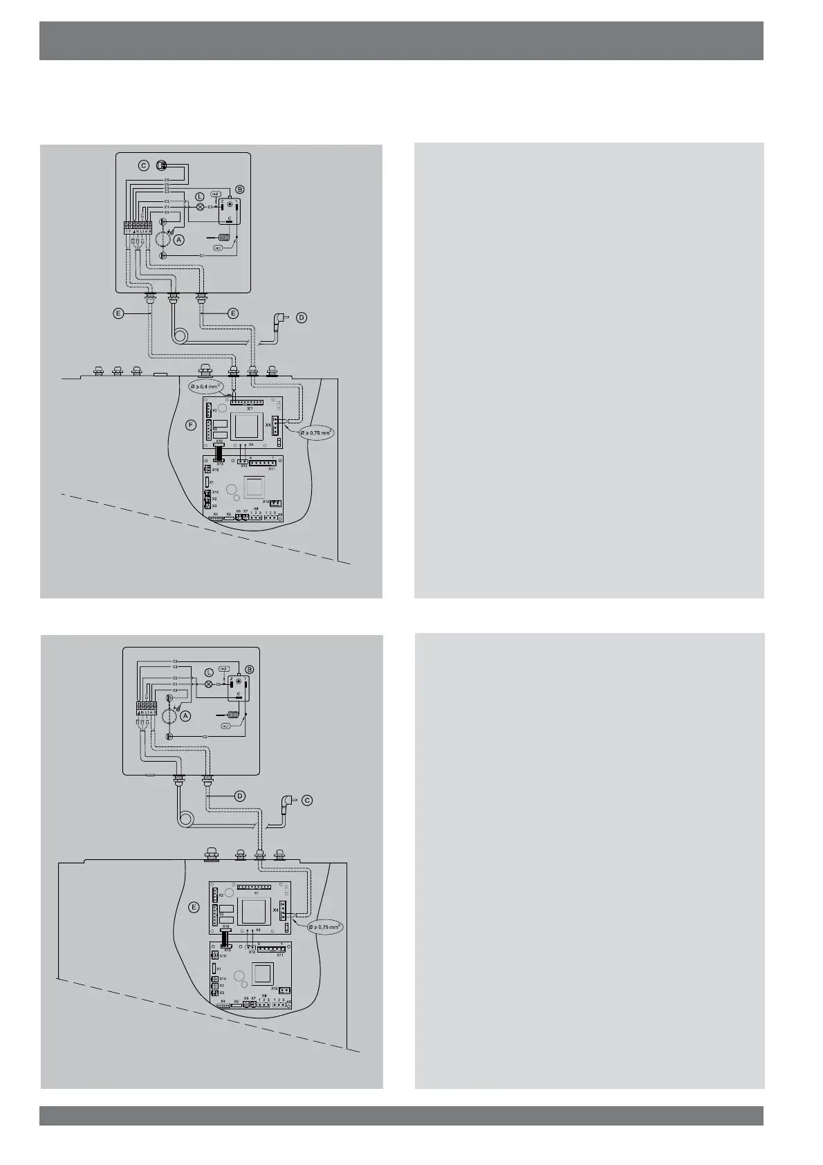
6.5 Wiring diagram postheater
A = Heating coil (max. 1000 W)
B = Maximum safety
C = Temperature sensor
' 3OXJ9
E = Cables to be connected by installer
F = Option pcb
L = LED maximum safety switched on
C1 = Brown
C2 = Blue
C3 = Green/yellow
C4 = Black
C5 = Yellow
The postheater sensor is connected to the X1 connectors no.
9 and no. 10 of the option pcb.
7KHSRVWKHDWHUFRQWUROVLJQDO9LVFRQQHFWHGWRWKH;
connectors no. 3 and no. 4 of the option pcb.
E2085-A
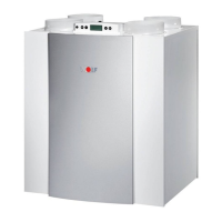
A = Heating coil (max. 1000 W)
B = Maximum safety
& 3OXJ9
D = Cable to be connected by installer
E = Option pcb
L = LED Maximum safety operational
C1 = Brown
C2 = Blue
C3 = Green/yellow
C4 = Black
7KHSUHKHDWHUFRQWUROVLJQDO9LVFRQQHFWHGWRWKH;
connectors no. 1 and no. 2 of the option pcb.
E2087-A
6.6 Wiring diagram preheater