Heat Recovery unit CWL-300(B) / CWL-400(B) with option PCB 5
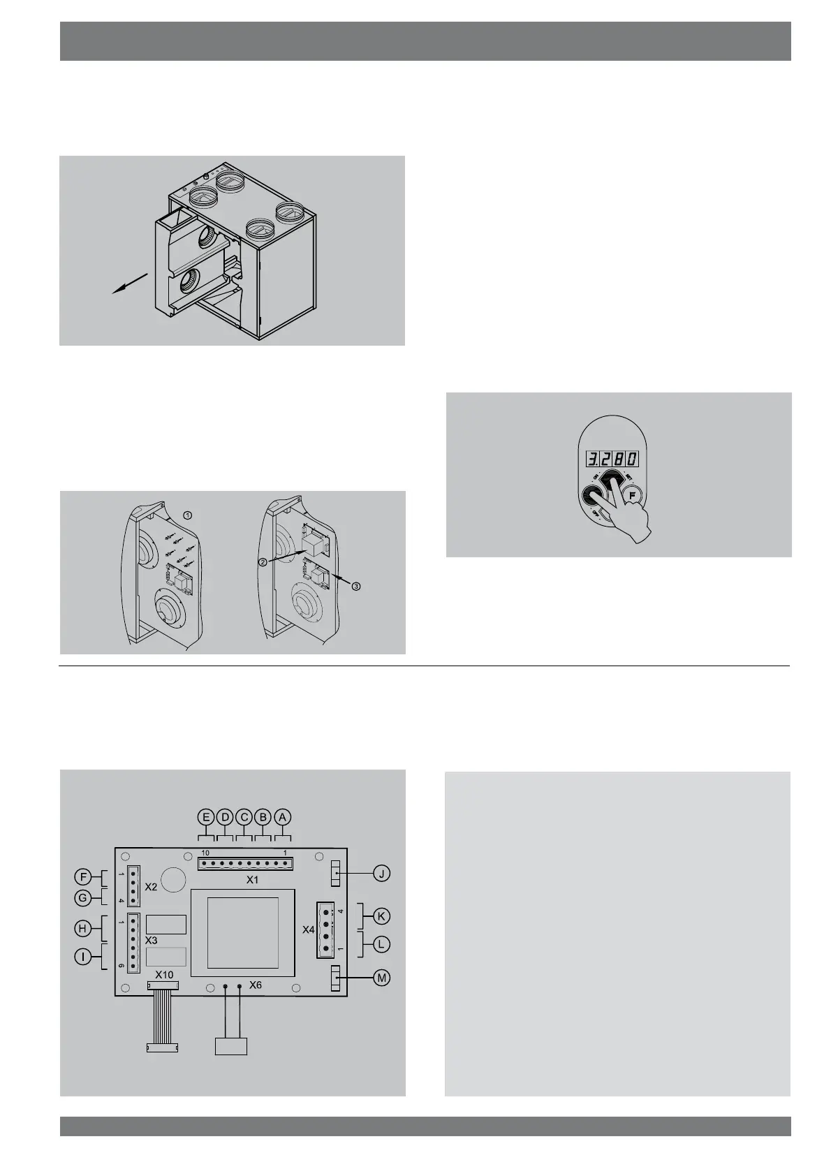
7 Slide the fan unit forward from the appliance far enough to
access the basic pcb.
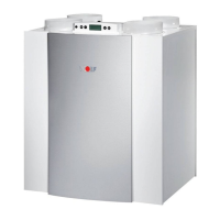
8 Mount the 6 pcb feet that came with the option pcb. Then
press the option pcb on the pcb feet and connect the 2
cables from the option pcb to the basic pcb (connector X12
and X13; see also §9.4 in the installation instructions CWL
300/400). Connect the desired options to the option pcb;
UHPRYHWKHVHDOLQJSOXJVPRXQWWKHQHFHVVDU\VZLYHOVLQ
the top panel and feed the additional cables through those
out of the appliance.
9 Slide the fan unit back into the appliance.
5H¿WWKHFRQWUROSDQHO)RUDQDSSOLDQFHZLWKE\SDVVXQLW
¿UVWPRXQWWKHKHDWH[FKDQJHUDQGWKHE\SDVVXQLW
11 Place the heat exchanger back into the appliance.
3ODFHWKHIURQWFRYHU
3ODFHWKH¿OWHUVLQWKHDSSOLDQFHZLWKWKHFOHDQVLGHIDFLQJ
the exchanger.
&ORVHWKH¿OWHUGRRUDQGVZLWFKRQWKHSRZHUVXSSO\
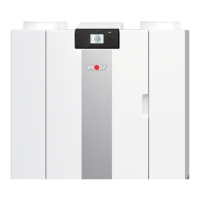
15 Switch on the appliance on the control panel (simultane-
ously press keys “OK” and “+“ for 3 seconds).
$IWHUFOHDQLQJWKH¿OWHURUDSODFLQJDQHZ¿OWHUWKH¿OWHULQ-
dication must be reset by pressing key “OK” for 1 second.
Assembly option PCB Chapter 2
5383-0
5442-0
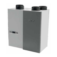
2.2 Connections option pcb
7KH RSWLRQ SFE LV ¿WWHG ZLWK D QXPEHU RI VFUHZ FRQQHFWRUV
7KHVHFDQEHXVHGWRFRQQHFWYDULRXVFRPSRQHQWV7KH¿JXUH
EHORZVKRZVWKHORFDWLRQRIWKHYDULRXVWHUPLQDOV
The moment the option pcb is connected, it will automatically
be detected by the basic pcb.
A = Switching input for incident
% 6ZLWFKLQJLQSXWIRUEHGURRPYDOYH
C = Programmable make contact P1
D = Programmable make contact P2
E = Temperature sensor postheater
F = Input moisture sensor
G = Input CO
2
sensor
+ 6ZLWFKLQJRXWSXWIRUEHGURRPYDOYH9$&
, 6ZLWFKLQJRXWSXWÀXHJDVYDOYH9$&
J = Fuse postheater 4AT
K = Switching output postheater
L = Switching output preheater
M = Fuse preheater 4AT