3040531_0711 11
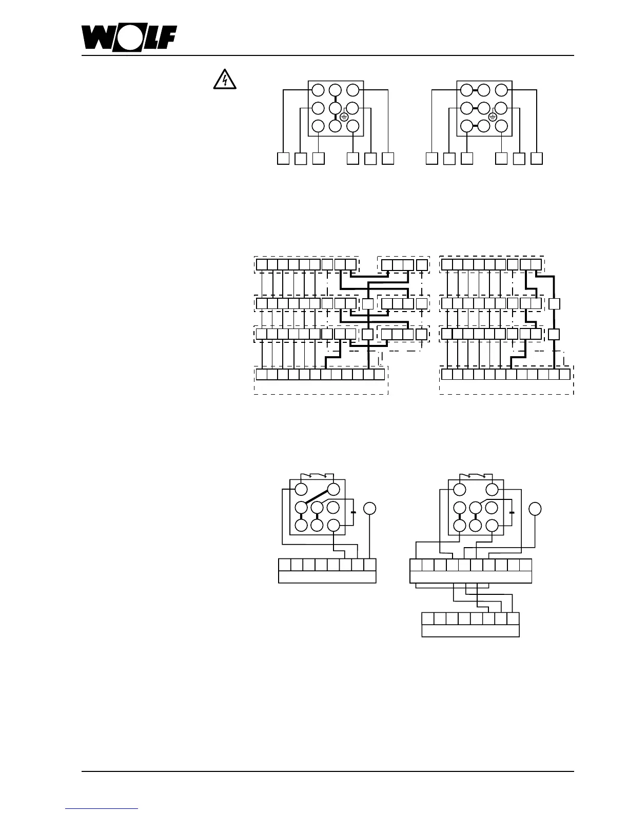
Operation of several LH-units with
one switch or control device
LH-units of different sizes and capacity
can be oberated with one switch up to the
max. permissible capacity or max. permis-
sible current of the switch.
When operating several LH-units, the mo-
tor terminals have to be switched parallel,
the thermal cutouts and anti-frost thermo-
stats in line! Terminal clamp 5 on site.
U1 V1
W1
W2 U2 V2 PE 12 11
U1 V1
W1
W2 U2 V2
TK TK R1 R2
5
PE
U1 V1
W1
W2
U2
V2 PE 12 11
5
U1 V1
W1
W2 U2 V2 PE 12 11
5
LH-unit with thermal cutouts
LH-step-switch or conrol device
(i.e. step-switch DS)
U1 V1
W1
W2 U2 V2 PE 12 11
124PE
U1 V1
W1
W2 U2 V2
TK TK R1 R2
5
PE
U1 V1
W1
W2 U2 V2 PE 12 11
124PE
5
U1 V1
W1
W2 U2 V2 PE 12 11
12
4
PE
5
LH-step-switch or control device
(i.e. step-switch DS)
LH-unit with termal cutouts
and anti-frost thermostat
L1
11 N12
PE
11
Z1
U1 Z2
12
U2
PE
PE N
L1
R1 R2 N
VM
PE
5-step-switch E5-3
Single-phase-AC-motors
230 V / 50 Hz
Single-phase-AC-motors are delivered
only in high-speed-wiring.
Wire thermal cutouts in line with motor
winding.
Speed control with 5-step-switch
type E5-...
Three-phase-motors
High speed
TKL3 TKL1
11W2
U1
PE
V1
12W1
V2
U2
PEL2
Low speed
TKL3 TKL1
11W2
U1
PE
V1
12W1
V2
U2
PEL2
Electrical Connection