3040531_07118
Installation Instructions
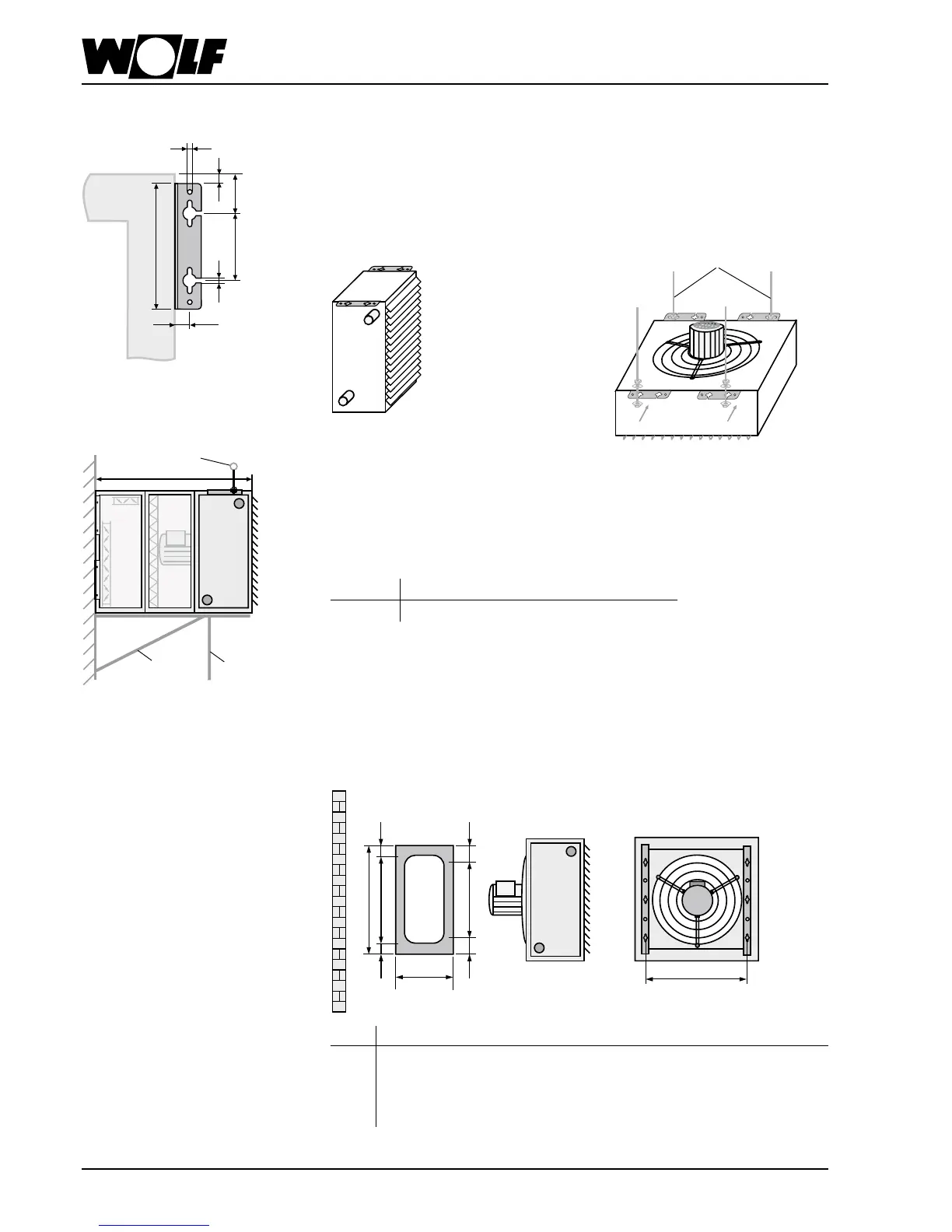
Suspension angles
Attach the suspension angles to LH-unit.
For mounting on the ceiling with horizontal air outlet, rst x screws Ø 8 mm (on site)
to the ceiling. Hang up LH-unit at key holes and tighten screws.
For sloping the LH-unit from the ceiling, insert threaded shaft (8 mm) from side through
slot of key holes and tighten by nut, counter-nut and 2 washers.
Depending on the construction of the ceiling, use appropriate screws and dowel pins,
if necessary.
Fix screws Ø 8 mm to wall.
Hang up LH-unit and suction accessory by means of key-holes and tighten screws.
For wall- mounted units exceeding a max. length Lmax. provide an additional support
or suspension on-site.
LH 100 with steel-galvanized heat exchangers type 2 and 3 require this additional
support or suspension already at a unit-length of L = Lmax.
LH 25 40 63 100
L
max.
[mm] 1100 1100 1100 1220
120
65
5
240
25
9
9
Threaded sheft
L
max
Suspension
Bracket
Support
Mounting brackets
Fit mounting brackets to LH-unit by means of enclosed screws.
Attach screws to wall of ceiling according to measure "c".
Hang up LH-unit by means of key holes of mounting brackets and tighten screws.
LH a b c d e f g h i
25 480 250 380 70 30 170 155 155 434
40 480 250 2 x 170 90 50 2 x 170 70 70 564
63 784 350 170+340+170 72 32 3 x 170 137 137 734
100 784 350 170+340+170 72 32 3 x 170 137 137 894
Dimensions en [mm]
a
c
l
b
f
d
g
h
e
x
x
x
x
x
x