supply
Control System WRS
Ventilation control unit LM1
with BML
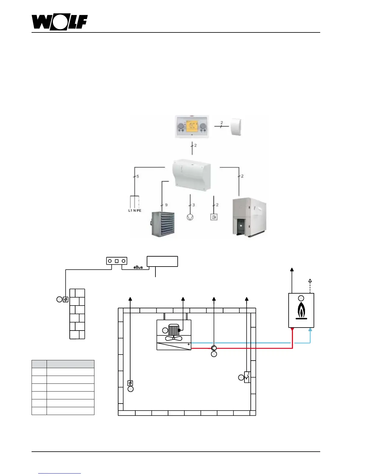
Installation diagram:
No. Description
1 room sensor
2 outside sensor
3 external release
4 2-stage motor
5 heating circuit pump
6 heat source
Description:
Example:
Unit heater, heating with room
temperature control
supply
unit heater
boiler
heating
circuit pump
room
sensor
BML
OS
LM1
This conguration is used for heating buildings in conjunction with air heaters. The
room temperature is captured by a sensor and the fan, the heating circuit pump and
the heat source are switched on or off depending on demand.
If the temperature deviation (set room temperature to actual room temperature) is low,
the fan is operated in stage 1. If the temperature deviation is greater, it is switched to
stage 2.