w
00
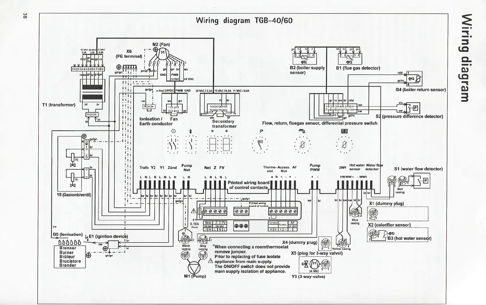
T1 (transformer)
YO(Gaskombiventil)
Wiring
TGB-40/60
diagram
X6 r.- M2(Fan)
(PE terminal) i
A
- M
~rrrrn . 32'
-'f'j";"')"j' I"'TT 12345
go/gn,. I , ,. gO/g~'lbrl gl kmobJ 1:.s
GNol I~WM
n-Halll 124 VDC
!! i i 1.':.:.-_'.-:...
iii:r-;::;;:
,
' ge/grr
~-'...!
'LII
!! ii
II' .
. .11
!! ii
!! ii
II' .
. .11
!! ii
II' .
, .11
_.I! ii
I' .
.11
I' ,
.11
!ii
I' .
.11
!i i
I' .
.1,
I' .
.1,
!ii
I' .
: : ~~~ffl'l~ r~ltf.~~J~lb~.-. -, -,.
~
gr/rs "I oG-t!
84 (boiler return sensor)
vio
I I Ii '/iiefgn gr/r.
Flow, return, fluegas sensor, differential pressure switch
vii>~!if
Secondary
transformer
.. ..
lonisation / Fan
Earth conductor
Trafa Y2
+
-
.' '. .' '.
~B~ ~8~
Pump
PWM
Net Z FV
Thermo- Access. AF
stat Bus
LNLNL ab+-+.
Printed wiring board
of control contacts
L N L N
,- .- .go/gn
bl
S1 (water flow detector)
"~~~
Rod
casing
X1 (dummy plug)
, , , ,
'
I(
,
. .
, .
. .
1.~ ~ !
,~~J!?~!!?~i.~.~r..~.~~.~~r.L ,
1.~~~.~~.~~.~.~~~~.~.~~.~Jr)
85 (Ionisation) L.E1 (igintion devicb)
- '+ Ibr
!)f)f)!)()f:> -~
p
~
Brenner @ ibl
-,-,-,-8,-,-,
Burner t;p. go/gn
Bruleur >0;;1
Bruciatore
Brander
ICiCi(i)1
I I..............
~2 ~2 X4 (dummy plug) 1~: ~"fi'>!I
Bla,ck G~y *When connectin
g a roomthermostat i ~ il~2
casing casmg . ;..~ ,Vollowcasmg
V
remove Jumper. X5 (plug for 3-way valvel)
PIP: Prior to replacing of fuse isolate [""""""""""""""""1
& appliance from main supply. :~:
The ON/OFF switch does not provide i ~-~:
main supply isolation of appliance. i ~.~.~~!:...~i
M1 (Pump) Y3 (3-way-valve)
~
-.
~
-.
~
~
c.
-.
Q,)
~
~
Q,)
3
p
";,\
m
"
, '
, .
\1',',
:.'
Z':
:, Z
.' . .'
CD
i!
, '.
.'
. I I. . I
::
:')
. ..
...
Y1 Zund
Pump
Net
L N L N
L N