Manual 35072 Vertex Compressor Control
Woodward 67
Along with possible compressor damage, the process flow and pressure become very unstable doing
surge contributing to upstream and downstream process upsets.
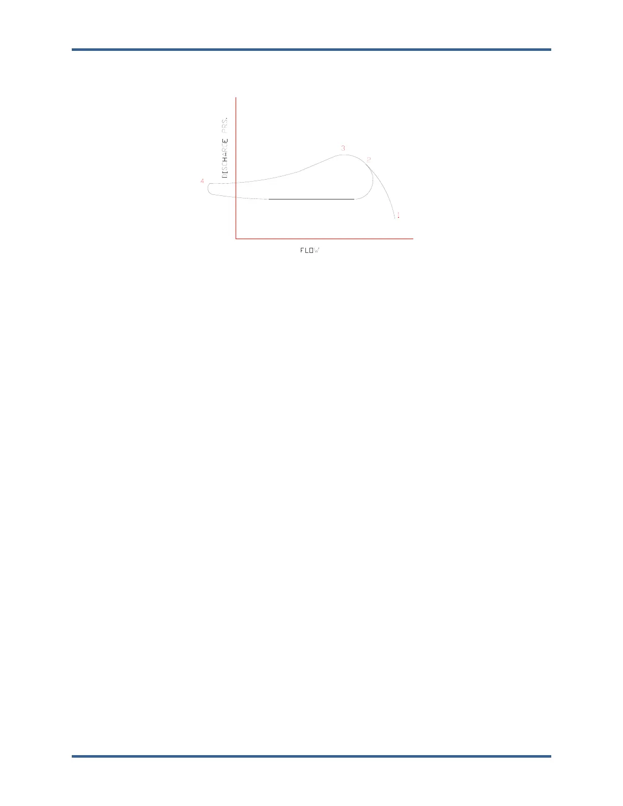
Figure 6-2. Surge Cycle
Figure 6-2 shows a typical surge cycle at a constant speed and constant suction density. The
compressor, operating at point 1, has low discharge pressure and the output flow is at its maximum value.
As the system resistance increases (e.g. discharge valve closes, downstream processes shutdown or
decrease load, series units drop off-line, or parallel units come on-line), the compressor flow decreases,
and discharge pressure increases. At operating point two, the compressor is near the surge limit. As the
system resistance increases further, the flow continues to decrease, and discharge pressure continues to
increase. Eventually, a limit is reached where the compressor can no longer increase discharge pressure,
such as at operating point 3. If the system resistance increases further, the discharge pressure becomes
greater than the machine’s capability. This initiates a surge that spans between points three and four.
Flow may actually reverse through the compressor, as shown at point four. A now reduced system
resistance will allow increased flow back through the compressor that brings the operation back to point
2. This surge cycle will continue until broken by some control or operator action.
Maintaining flow above the compressor’s surge limit prevents these surge conditions. The controller must
continually monitor the operating point and compare it to the surge limit of the compressor. If the
operating point reaches a minimum flow value, the controller responds by opening the anti-surge valve(s).
This simultaneously causes the flow to increase and discharge pressure and polytropic head to decrease,
moving the operating point away from the surge limit.
Anti-Surge Control Theory
By modulating the anti-surge valve, the anti-surge controller maintains certain process conditions to:
Prevent the compressor from operating in an unstable condition (surge or near surge), thereby
preventing any surge related compressor damage.
Reduce process upsets.
Maximize the compressor and total train efficiency.
In order to perform these tasks, the controller must monitor the parameters of current operating point, and
compare it to the known parameters on the Surge Control Line (SCL), and determine if opening of the
anti-surge valve is necessary.
The compressor performance map describes the relationship between speed, pressures, temperatures,
gas properties, and inlet flow. This map also describes the operating limits of the compressor in terms of a
Surge Limit Line (SLL) or surge region. Several variations are possible on how this information is
presented, each describing the compressor with a different set of variables.

 Loading...


