INSTALLATION
6 720 644 743a (2010/10)
33
4.5.4 FLUE TERMINAL PLUME RE-DIRECTION
The flue discharge can be re-directed allowing some
plume redirection control, alternatively, a complete
plume management system can be fitted to the flue
terminal.
RE-DIRECTING THE FLUE DISCHARGE
1. Remove screws (1) and rotate the terminal end (2)
through 180°.
1. Refit the terminal end (2) and secure with screws (1).
2. Loosen screws (3) and rotate the entire outlet
assembly to redirect the plume. Tighten screws (3) to
secure in the required position.
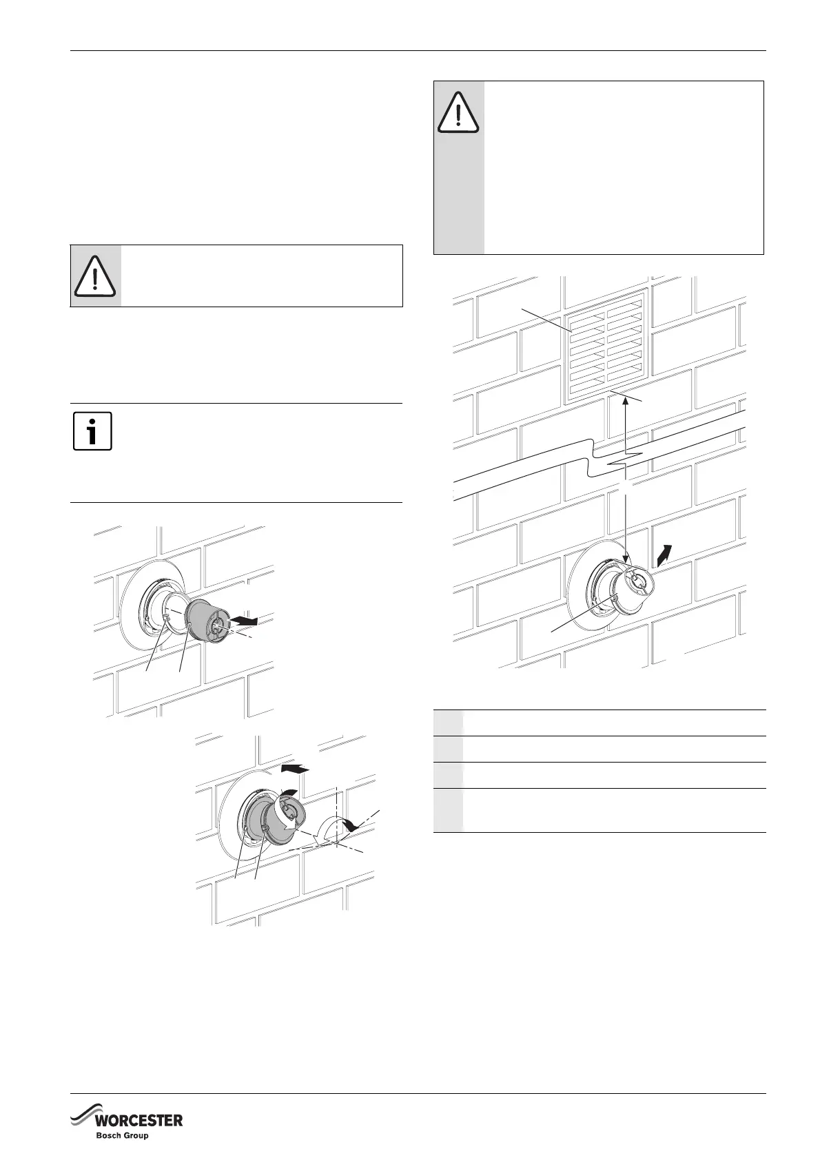
Fig. 44 Plume redirection
Fig. 45 Plume distance to opening
NOTICE: DO NOT rotate the complete
terminal assembly.
The flue terminal outlet has built-in stops to
limit rotation for horizontal flue to allow
condensate to run back into the boiler for
safe disposal. Do not attempt to force
beyond the limit stops.
1
2
1.
3.
2.
3
1
±80°
180°
6720643895-34.1Wo
NOTICE: Outlet position
B The flue terminal outlet position must
follow those stated in the relevant
appliance instruction manual.
When redirecting the flue discharge the
outlet terminal must be at least 1500mm
from any opening in the direction of the
discharge to prevent combustion
products from entering the building.
1 Opening in building
2 Flue discharge
3Plume deflector
4 Minimum 1500mm from an opening in the
building
Tab. 20 Key to figure 45
6720643895-119.1Wo
1
3
4
2



 To Next Page