FAULT FINDING AND DIAGNOSIS
6 720 644 743a (2010/10)
65
7 FAULT FINDING AND DIAGNOSIS
7.1 FAULT FINDING
The electronic control system for this boiler
incorporates a blue central indicator. This normally
confirms the permanent mains supply but, by flashing at
different rates during a fault, provides a guide to the
cause as listed.
This fault finding system assumes that the appliance has
been operating normally until the time of failure (i.e. not
a first installation error).
PRELIMINARY CHECKS : Preliminary electrical system
checks are the first electrical checks to be carried out
during a fault-finding procedure. On completion of the
Service/Fault-Finding task which has required the
breaking and remaking of electrical connections, check:
(a) EARTH CONTINUITY,
(b) SHORT CIRCUIT CHECK,
(c) POLARITY and
(d) RESISTANCE TO EARTH.
This fault finding information is for guidance
only. Worcester cannot be held responsible
for costs incurred by persons not deemed to
be competent.
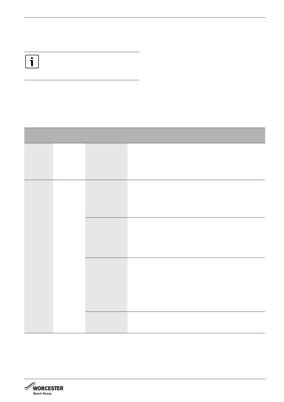
Blue light
indication
Lockout
reset button
Fault Possible solution/check
Off Off No power at
control board
Permanent mains supply to boiler.
Fuse F1 - 2.5A or Fuse F3 - 0.5A.
Transformer (primary coil below 60 Ω, both secondary coil
below 10 Ω).
Otherwise replace control board.
On Off Boiler not
operating during
central heating
demand (HW ok)
Live demand at ST10-L
R
(from external room thermostat/timer)
Fascia mounted timer (if fitted)
CH knob in winter position
Diverter valve
Control board
Boiler operating
without live
demand at ST10-
L
R
(from external
room thermostat
timer)
Some older thermostats (containing capacitors) may give a low
voltage return at ST10-L
R
when the thermostat contacts are
open.
Check that there is no permanent live at ST10-L
R
from another
source.
Boiler not
operating during
hot water
demand (CH ok)
Ensure cold inlet DHW outlet are correctly piped i.e. are not
crossed piped.
Flow Turbine test:
B Check for 5 volts d.c. across red and black wires
B Check for 2.5 volts d.c. across the yellow and red wires with
the water flowing.
Check diverter and motor and control board.
Boiler not
operating during
any demand.
Fan
Control board
Tab. 26



 To Next Page