INSTALLATION
6 720 644 743a (2010/10)
35
4.7 ELECTRICAL
The mains supply to the boiler must be either:
• The mains electrical supply to the boiler and system
wiring centre must be common and through either a
common fused double pole isolator or a fused three
pin plug and unswitched socket.
• The isolator shall be situated next to the boiler for
new systems and, where practicable, replacement
boilers.
• The isolator must have a contact separation of 3mm
minimum between all poles. Any system connected to
the boiler must not have a separate electrical supply.
• Use a 3A fuse in both situations.
ACCESS TO ELECTRICAL CONNECTIONS:
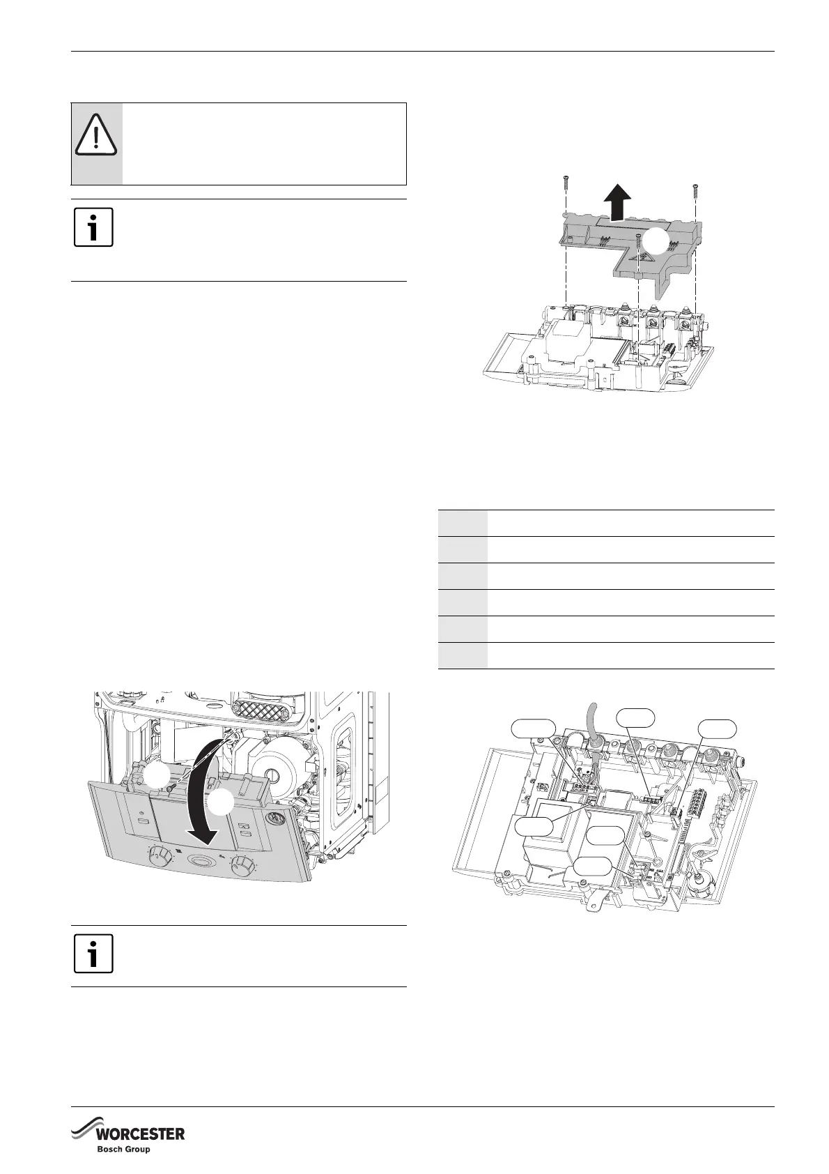
B Remove boiler casing to access control panel.
Refer to figure 50.
1. Remove the screw securing the control panel.
2. Lower the control panel into the horizontal service
position.
Fig. 50 Moving control panel into the service position
Refer to figure 51.
1. Unscrew the three screws in the control panel.
2. Pull off the connections cover.
Fig. 51 Removing the connection cover
B Pass the 230 V mains power cable, from the control
box, through the grommet at the right hand side of the
pre-plumbing manifold and route to the mains isolator
next to the boiler.
Fig. 52 Electrical connector information
CAUTION: ISOLATE THE MAINS
ELECTRICITY SUPPLY BEFORE STARTING
ANY WORK AND OBSERVE ALL RELEVANT
SAFETY PRECAUTIONS.
The boiler is pre-wired with a two metre
mains supply cable.
A spare strain relief block is supplied in case
the pre-wired cable is not used.
When stripping wires always ensure copper
strands do not fall into the control box.
1.
2.
6720644743-18.1Wo
SI1 Fuse F1 2.5A
SI2 Fuse F2 0.5A
SI3 Fuse F3 1.5A
ST6 Frost thermostat connection
ST10 Mains in & external controls connections
ST19 EMS bus connection
Tab. 21
1.
1.
1.
2.
6720643895-40.1Wo
6720644743-19.1Wo
ST10
ST6
SI2
SI3
SI1
ST8



 To Next Page