Pre-Installation
6 720 811 922 (2014/07) 13
3.6 BOILER LOCATION AND CLEARANCES
3.6.1 INSTALLATION
This boiler is only suitable for installing internally within a property at a
suitable location onto a fixed, rigid surface at least the same size as the
boiler and capable of supporting the boiler weight.
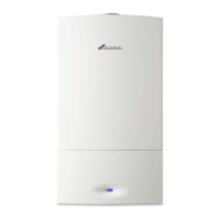
3.6.2 INSTALLATION AND SERVICING CLEARANCES -
UNVENTILATED COMPARTMENTS
Fig. 15 Compartment clearances
[*] Minimum clearance to removable door
[**] Minimum clearance required for servicing
[***] Minimum clearance required to remove expansion vessel with
boiler mounted with left or right flue exit
3.6.3 COMPARTMENTS
Follow the requirements of BS6798 and BS5440 Part 2 and note:
• Minimum clearances must be maintained.
• An access door is required to install, service and maintain the boiler
and any ancillary equipment.
• If fitting the boiler into an airing cupboard use a non-combustible
material to separate the boiler from the airing space.
The material can be perforated up to a maximum hole size of 13mm.
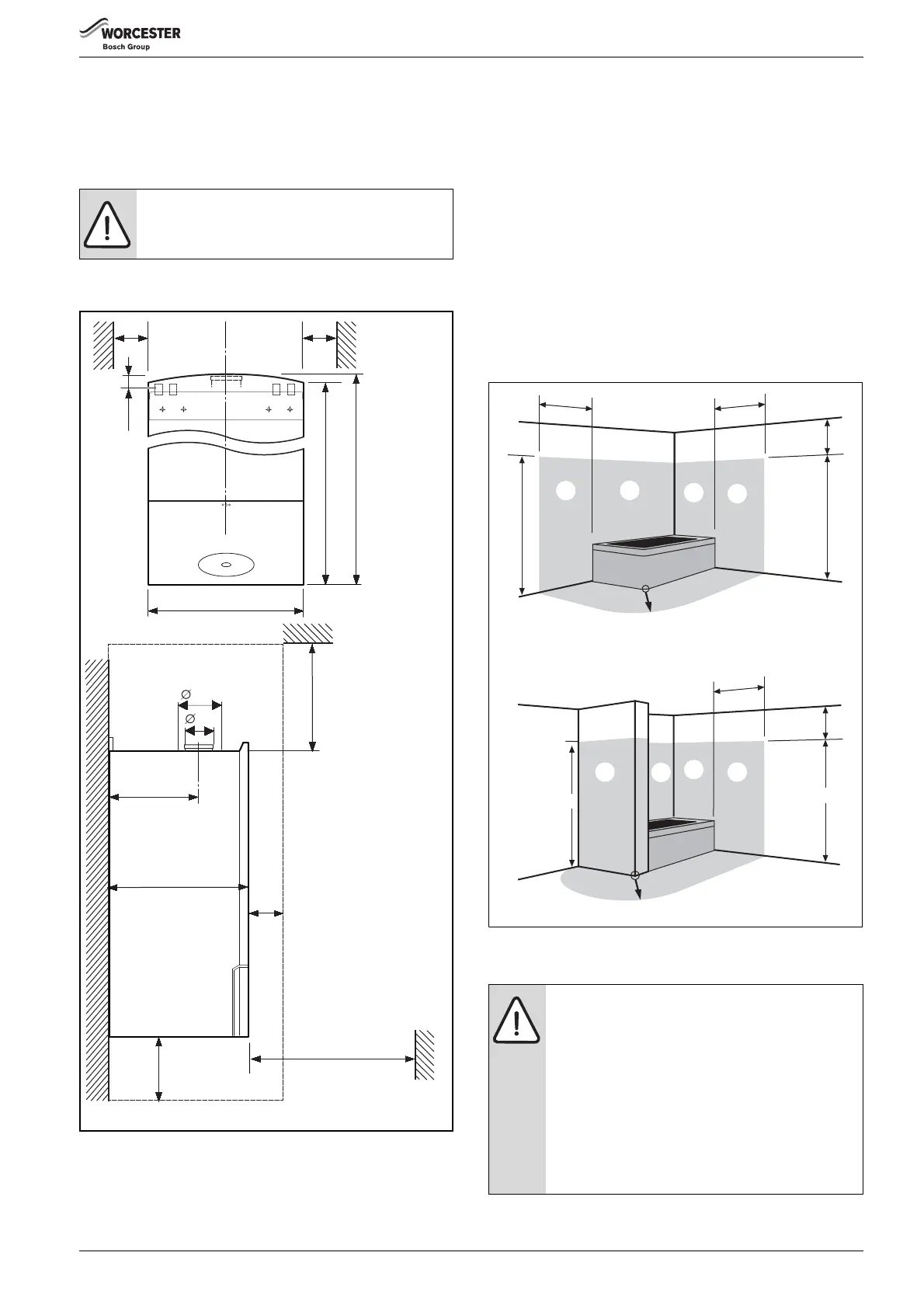
3.6.4 BATHROOMS
A boiler fitted with a mechanical timer or RF mechanical timer (receiver)
or FW100 controller may only be installed outside the shaded area.
A boiler with any other timer fitted (or blanking panel) can also be
installed in zone 2.
Additional RCD (Residual Current Device) protection may be required.
Consult the latest version of BS7671 (IEE wiring regulations).
Fig. 16 Bathroom installations
3.7 FLUE OPTIONS
NOTICE:
No surface protection is required against heat transfer
from the boiler
min.
10
min.
10
400
15
840
850
6720800945-02.1Wo
370
200**
170 (60/100 flue)**
210 (80/125 flue)**
400 ***
600**
20*
218
125
80
CAUTION: Non accessible flue systems:
▶ Where a flue system is not going to be accessible,
provision must be made for service and inspection.
▶ Voids containing concealed flues must have at least
one inspection hatch no less than 300mm square.
▶ Flue joints within the void must not be more than 1.5
metres from the edge of the inspection hatch.
▶ Inspection hatches should be located at changes of
direction.
▶ If this is not possible, bends should be viewable from
both directions.
600mm radius
600 mm
600 mm
750 mm
2250 mm
2250 mm
600 mm
2250 mm
600mm radius
750 mm
2250mm
6720643895-10.1Wo
1
1
1
1
2 2
2
2
 Loading...