Service
6 720 811 922 (2014/07) 39
▶ Remove sealing plug from air inlet sample port [2].
▶ Insert a flue gas probe into the test port and seal the test port
▶ Press the Central heating boost button until the button illuminates
and press once again to select = maximum rated output.
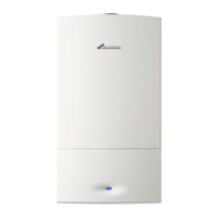
Fig. 62 Flue test ports
[1] Flue gas sample port
[2] Air Inlet sample port
▶ Allow the readings to stabilise and measure the O
2
and CO
2
levels.
▶Refit sealing plug.
8.4 MEASURING CO CONTENT OF FLUE GAS
Use a multiport flue gas probe for this test.
▶ Remove sealing plug from flue gas sample port [1].
▶ Insert a flue gas probe as far as it will go into the test port and seal the
test port.
▶ Press the Central Heating boost button until the button illuminates
and press once again to select = maximum rated output.
▶ Run the boiler at maximum output for at least 10 minutes.
▶ Measure the CO levels.
▶ Repeatedly press the Central Heating boost button until the light
extinguishes.
The display will show the CH flow temperature.
▶Refit sealing plug.
8.5 SETTING GAS/AIR RATIO (CO
2
)
▶ Switch appliance off at the ON/OFF switch.
▶ Remove the outer casing.
▶ Switch appliance on at the ON/OFF switch.
▶ Remove sealing plug from flue gas test port (1).
▶ Insert a flue gas probe approx. 135 mm into the test port socket (1)
and seal the port.
▶ Hold down the Central Heating boost button until it illuminates.
Press the button once again and the display shows the flow
temperature alternating with = maximum rated output.
▶ Measure the CO
2
level.
▶ Using a 2.5mm Allen key, adjust the gas flow throttle [3] to set the
CO
2
level for maximum rated output according to the table.
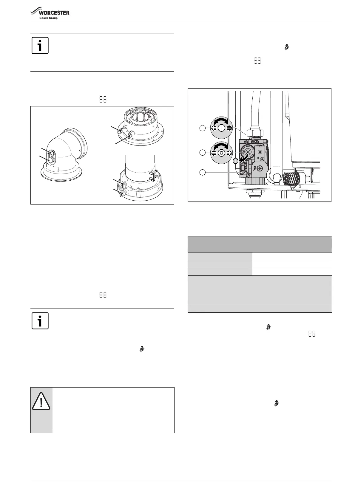
Fig. 63 Gas valve adjustment
[1] Gas supply pressure test port
[2] Adjusting screw for min. gas supply flow rate
[3 ] Adjusting screw for max. gas supply flow rate
▶ Press Central Heating boost button once again.
The display shows the flow temperature alternating with =
minimum rated output.
▶ Measure the CO
2
level.
▶ Using a flat blade screwdriver, remove the dust cap from gas valve
adjusting screw
▶ Using a 4 mm Allen key, set CO
2
level for minimum rated output.
▶ Replace the dust cap after adjustment.
▶ Re-check settings at maximum and minimum rated output and re-
adjust if necessary.
▶ Record the CO
2
levels in the Benchmark Commissioning checklist.
▶ Press the Central Heating boost button again and the light will
extinguish.
The display will show the CH flow temperature.
▶ Remove flue gas probe from flue gas test port (1) and refit sealing
plug.
With a type C
13
, C
33
or C
53
flue system, the gas
tightness of the flue system can be tested by
measuring the O
2
or CO
2
content of the combustion air.
The O
2
level must exceed 20.6%. The CO
2
level must not
exceed 0.2 %.
The CO must be less than 200 ppm
(0.002 ratio)
NOTICE: Gas/Air ratio
▶ Setting the gas/air ratio must be carried out by a
competent person. Testing must not be attempted
unless the person carrying out the combustion check
is equipped with a Combustion Analyser conforming
to BS 7927 and is competent in its use.
Gas type
CO
2
CO
2
Max. output Min. output
Natural gas H (23) 9.6 % 8.7 %
Checking tolerance 0.5 0.5
Adjustment tolerance 0.3 0.4
When checking an existing appliance the tolerance is 0.5%.
If checking after cleaning or component replacement or for adjustment
when the reading obtained is outside the tolerance given in table 25,
then the tolerance is 0.3 for maximum and 0.4 for minimum.
CO - less than 200 ppm (0.002 ratio)
Table 25 CO/CO
2
Tolerances
 Loading...