Fault finding
6 720 811 922 (2014/07)48
12 FAULT FINDING
12.2 FAULTS THAT ARE DISPLAYED
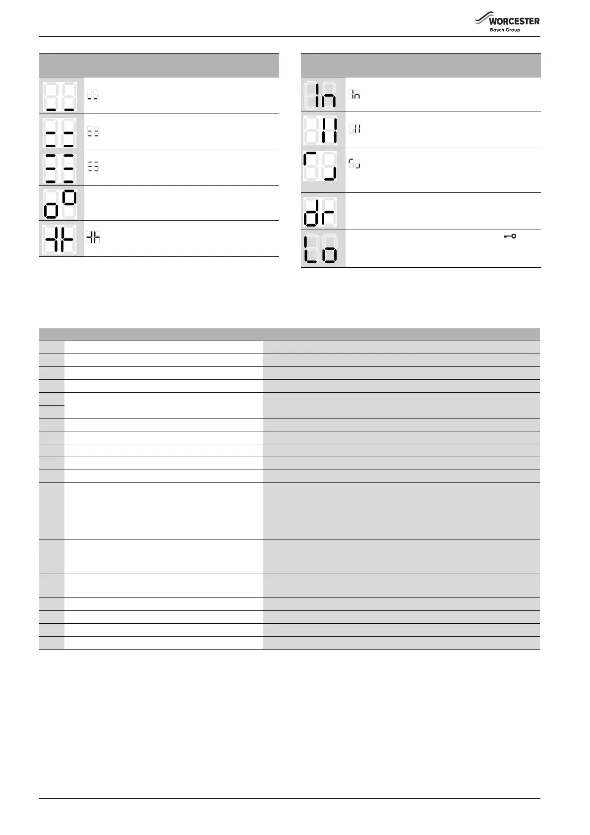
The display shows the flow temperature alternating with
. The appliance operates for 15 minutes at the
minimum rated output.
The display shows the flow temperature alternating with
. The appliance operates with the set maximum rated
output in central heating mode, service function 1.A.
The display shows the flow temperature alternating with
. The appliance
operates for 15 minutes at the maximum rated output.
Vent function active, see service function 2.C.
The display shows the flow temperature alternating with
. The syphon fill program is active, service
function 4.F.
Special
display Description
Table 29 Special displays
The display shows the flow temperature alternating with
: the set inspection interval has elapsed, service
function 5.A.
The display shows the flow temperature alternating with
. The heating circuit pump is blocked.
The display shows the flow temperature alternating with
. The temperature gradient limiter is enabled.
Excessive flow temperature increase: central heating
mode is suspended for two minutes.
Screed drying function of the weather-compensated
controller ( operating instructions) or building drying
function ( service function 7.E) operational.
Key lock enabled. To reset the key lock, press until
the flow temperature is shown on the display.
Special
display Description
Table 29 Special displays
Display Remedy
A7 DHW temperature sensor faulty. Check the temperature sensor and connecting lead for breaks or short circuits.
A8 Communication fault. Check BUS device connecting lead.
Ad Cylinder temperature sensor not detected. Check cylinder temperature sensor and connecting lead.
b1 Code plug not detected. Insert code plug correctly, test and replace if necessary.
b2 Internal data error. See servicing instructions for heating contractors.
b3
C6 Fan not running. Check fan lead and connector, check fan, replace as necessary.
CC Outside temperature sensor not detected. Check outside temperature sensor and connecting lead for breaks.
d3 External limiter has tripped. Temperature limiter TB1 has tripped. Jumper across 8-9 or PR-P0 is missing.
d5 External primary NTC on low loss header defect. Check NTC and cable continuity.
E2 Temperature sensor in CH flow faulty. Check the temperature sensor and connecting lead.
E9 Heat exchanger temperature limiter or flue gas
temperature limiter has tripped.
or
Flue pipe is blocked.
Check system pressure, temperature limiter, pump operation, fuse on PCB bleed
appliance. Check water-side of heat exchanger. On appliances with displacement
bodies in heat exchanger, check whether displacement bodies are fitted. Check
the flue (fresh air or exhaust gas) pipe blockage, check air pressure switch and air
pressure switch pipe. Check heat exchanger high limit stat and flue high limit stat.
EA Flame not detected. Is gas tap open? Check gas supply pressure, mains power connection, electrodes
and leads, flue pipe, gas-air ratio.
On natural gas appliances, check external gas flow switch.
F0 Internal fault. Check electrical connectors and ignition leads, replace PCB if necessary. Check
gas-air ratio.
F1 Internal data error. See servicing instructions for heating contractors.
F7 A flame is detected although the appliance is switched off. Check electrodes. Flue system OK? Check PCB for moisture.
FA A flame is detected after the gas has been switched off. Check gas valve. Clean condensate trap and check electrodes. Flue system OK?
Fd Reset was pressed in error. Press reset again.
Table 30 Displayed faults
 Loading...