Service
6 720 811 922 (2014/07)38
SERVICE FUNCTION B.F: START DELAY
This service function allows you to set the time in seconds before the
appliance starts DHW heating. Set the start delay in accordance with
system conditions.
The start delay can be set between 0 - 50 seconds.
Standard setting is 00 (disabled).
8SERVICE
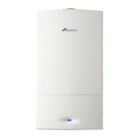
8.1 CHECKING THE GAS SUPPLY PRESSURE
▶ Switch off the appliance and turn off the gas tap.
▶ Undo the plug on the test port for gas supply pressure and connect a
pressure gauge.
Fig. 59
▶ Turn on the gas tap and switch on the appliance.
▶ Hold down the Central Heating boost button until it illuminates.
The display shows the flow temperature alternating with =
maximum heating output setting.
▶ Press the Central Heating boost button again and the display will
show the flow temperature alternating with = maximum rated
output.
▶ Check that the gas working pressures in the system conform to the
figures shown below:
Fig. 60 Natural gas pressure
▶ Repeatedly press the Central Heating boost button until the light
extinguishes.
The display will show the Central Heating flow temperature.
▶ Switch off the appliance, turn the gas tap to OFF, remove the
pressure gauge and refit the plug.
▶ Refit the outer casing.
8.2 CHECK FLUE INTEGRITY
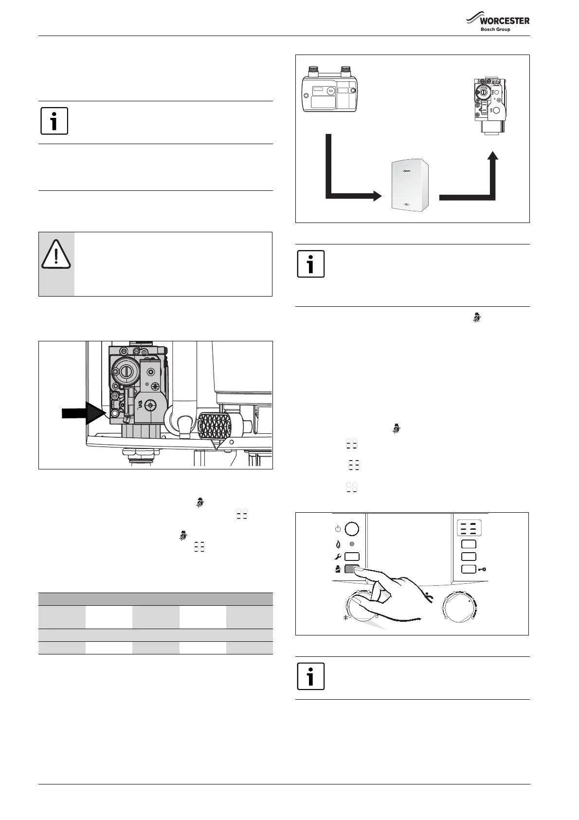
Central Heating boost button
The following appliance output can be selected by holding down the
Central Heating boost button until it illuminates:
• 1st press = = maximum heating output setting
• 2nd press = = maximum rated output
• 3rd press = = minimum rated output
• 4th press = EXIT from Central Heating boost.
Fig. 61
8.3 CHECKING FLUE SYSTEM FOR TIGHTNESS
Measure the CO
2
levels in combustion air.
Use an annular-gap flue gas probe for this test.
If a start delay is set, the demand signal is no longer
possible page 32.
NOTICE:
▶ Ensure that the gas pressure is satisfactory with all
other gas appliances working.
▶ Do not continue with the other checks if the correct
gas pressure can not be achieved.
Allowed mbar pressure drop
meter/
regulator
across
pipework
boiler inlet across
boiler
gas control
valve
Natural gas
19 - 23 1 18 - 22 1.5 16.5 - 20.5
Table 24
The appliance must not be operated if the pressure is
above or below these figures. Determine the cause and
correct the fault. If that is not possible, securely seal off
the gas supply to the appliance and contact the gas
supply utility.
You have 15 minutes in which to measure the levels.
After that, the appliance reverts from “boost” mode to
standard mode.
Meter
Boiler inlet
Gas Control
valve
19 - 23 mbar
18 - 22 mbar
16.5 - 20.5 mbar
1 mbar
drop
1.5 mbar
drop
Natural Gas
6720644744-44.1Wo
max
1
2
3 4
5
6
eco
reset
6 720 615 065-18.1O
max
1
2
3
4
e
6
min
 Loading...