COMMISSIONING
6 720 648 726 (2011/07)
56
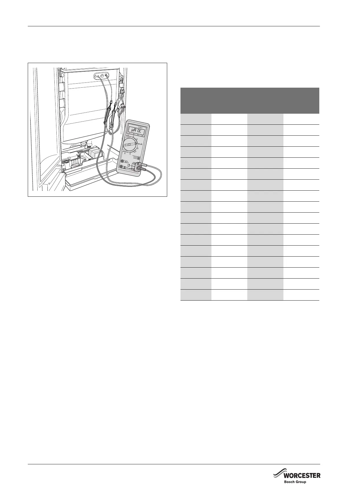
B Connect the multimeter in series. Select the μA DC
range on the multimeter. The multimeter must have a
resolution of at least 1 μA.
Fig. 93 Measuring the ionisation current
B Switch on the heating system by pressing the mains
switch of the BC10 basic controller (Æ fig. 90, [1]).
B Activate the Service mode in accordance with the
"Service mode" menu (Æ table 11, page 43).
B Set the capacity to minimum (part load) according to
the "Service mode" menu (Æ table 11, page 43).
B After the "Burner" LED (Æ fig. 90, [6]) has lit up wait
for one minute until the boiler is burning at part load.
B Measure the ionisation current. The ionisation current
must be > 5 μA DC at part load operation.
B Enter the result in the commissioning log book
(Æ section 10.5 "Commissioning record log book",
page 59).
B If the result is not as it should be, check the gas/air
ratio (Æ section 10.2.7, page 52) or check the
ionisation electrode (Æ section 13.2.4, page 66).
B Press and hold the "Chimney sweep" button
(Æ fig. 90, [3]) (approx. two seconds), until the dot in
the right-hand bottom corner of the display
(Æ fig. 90, [9]) appears. See also table 10, "Flue gas
test", page 42.
B Switch off the heating system by pressing the mains
switch of the BC10 basic controller Æ fig. 90, [1]).
B Remove the multimeter and reconnect the monitoring
cable.
B Switch on the heating system by pressing the mains
switch of the BC10 basic controller (Æ fig. 90, [1]).
B Check that the boiler performance is still at the
required value. See the "Service mode" menu
(Æ table 11, page 43).
10.3 BOILER SETTINGS
10.3.1 SETTING THE HEATING CAPACITY
B Set the required heating capacity on the BC10
according to the "Settings" menu (Æ table 13,
page 45). See table 16 when making these settings.
6 720 648 726-093.1TD
Display
indication
[%]
Rated heating capacity at 40/30 °C [kW]
GB162-65 GB162-80 GB162-100
L20 15.6 –21.1
L25 18.7 21.1 26.0
L30 21.8 25.3 30.9
L35 24.9 29.6 35.8
L40 28.0 33.8 40.7
L45 31.1 38.0 45.8
L50 34.2 42.2 50.5
L55 37.3 46.5 55.4
L60 40.4 50.7 60.3
L65 43.5 54.9 65.2
L70 46.6 59.1 70.1
L75 49.7 63.4 75.0
L80 52.8 (
1)
50)
1) Capacity at BC10 basic controller with removed jumper
67.6 79.9
L85 55.9 (
1)
50) 71.8 84.8
L90 59.0 (
1)
50) 76.0 89.7
L95 62.1 (
1)
50) 80.3 94.6
L-- 65.2 (
1)
50) 84.5 99.5
Table 16 Heating capacity in kW (as a percentage)
 Loading...


