TECHNICAL SPECIFICATIONS
6 720 648 726 (2011/07)
83
15 TECHNICAL SPECIFICATIONS
The technical specifications serve to provide information about the boiler performance profile.
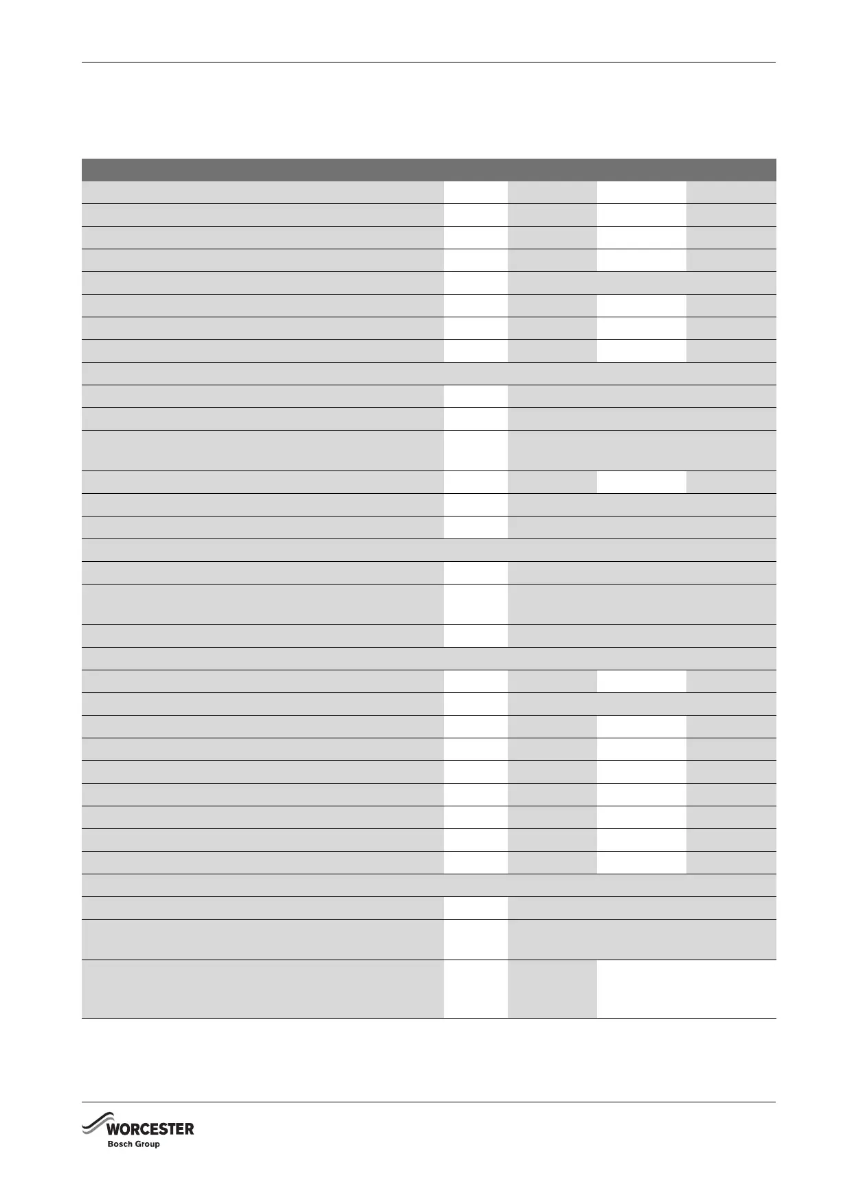
Unit GB162-65 GB162-80 GB162-100
Rated thermal load for G20 kW 14.6 - 62.0 19.3 - 82.0 19.3 - 96.5
Rated heating capacity, heating curve (80/60 °C) kW 14.2 - 60.5 18.9 - 80.0 19.0 - 94.5
Rated heating capacity, heating curve 50/30 °C kW 15.6 - 65.0 20.8 - 84.5 20.5 - 99.5
Boiler efficiency at max. capacity, heating curve 80/60 °C % 97 97 98
Boiler efficiency at max. capacity, heating curve 50/30 °C % 107
Rated efficiency, heating curve 75/60 °C % 106 107 107
Rated efficiency, heating curve 50/30 °C % 108 110 110
Standby heat loss % 0.05 0 .5 0.06
Hot water circuit
Minimum water circulation volume l/h 0
Maximum volume flow l/h 5,000
CH (boiler) flow temperature °C 30 – 90, can be set on the
BC10 basic controller
Resistance at ΔT
20
mbar 170 225 320
Max. boiler working pressure bar 4
Content of heating circuit heat exchanger l 5
Pipe connections
Gas connection inch G1“
Heating water connection inch G1½“ union nut with female thread
enclosed
Condensate water connection mm Ø 24
Flue gas values
Condensate water quantity for natural gas G20, 0/30 °C l/h 6.9 9.0 10.8
pH value of condensate water pH approx. 4.1
Flue gas mass flow rate, full load g/s 27.2 35.3 44.9
Flue gas temperature 80/60 °C, full load °C 64 67 76
Flue gas temperature 80/60 °C, part load °C 57 61 57
Flue gas temperature 50/30 °C, full load °C 43 48 51
Flue gas temperature 50/30 °C, part load °C 33 34 34
CO
2
content at full load, natural gas G20 % 9.4/9.2 9.3 9.4
Free fan feed pressure Pa –139220
Flue gas connection
Flue gas value group for air intake/flue gas system II
6
(G61)
Ø flue gas system, room-air dependent mm Ø100 or Ø110 (Ø100 with air intake
strainer basket, accessory)
Ø flue gas system, room-air independent mm standard
Ø80/125
concentric
standard Ø100/150
concentric
Table 25 Technical specifications
 Loading...


