Installation
6720813174 (2014/09) 7
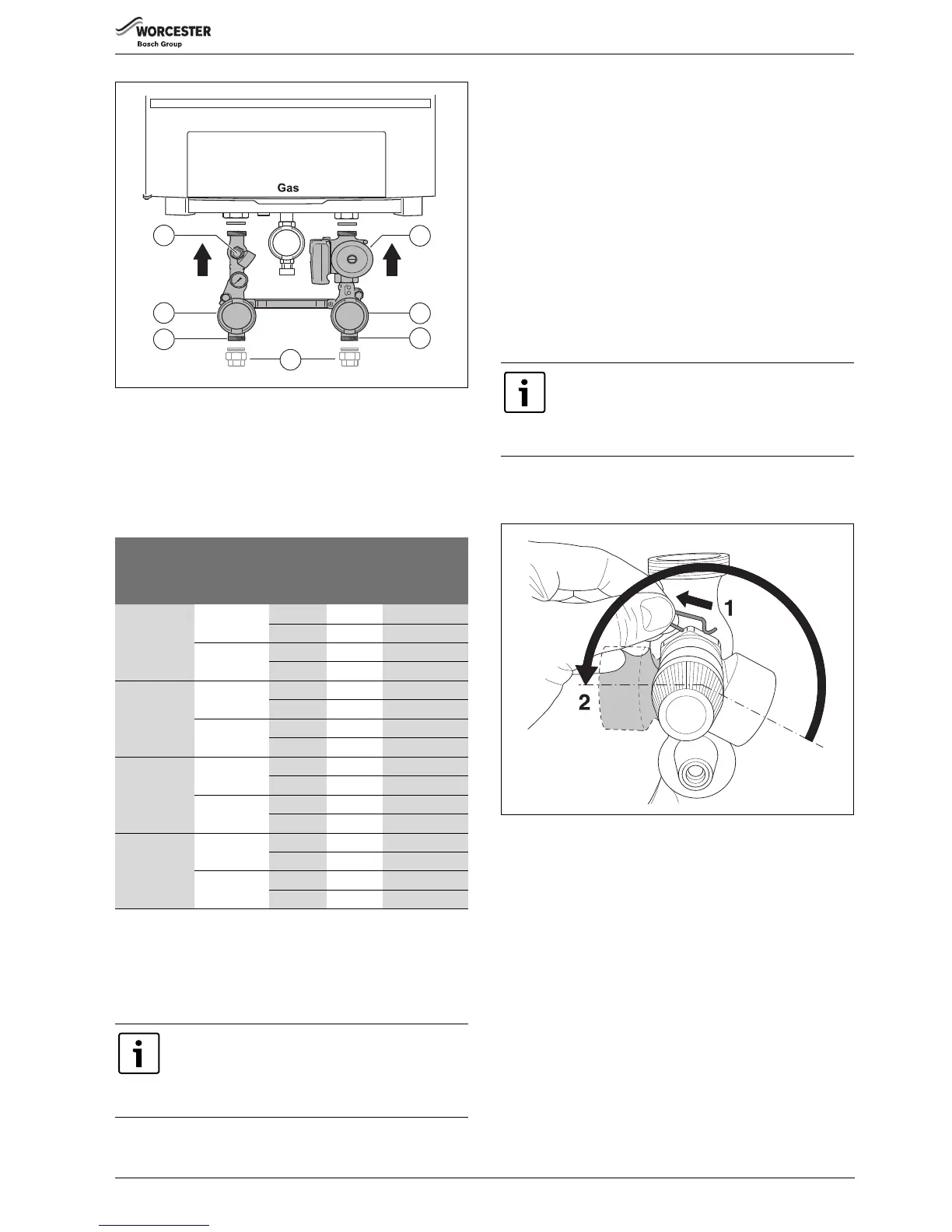
Fig. 9 Installing the isolating valves
[1] Pressure relief valve
[2] Isolating valve, red
[3] Flow connection
[4] Screw fitting 1" female thread (accessory)
[5] Pump
[6] Isolating valve, blue
[7] Return connection
▶ Install a shut-off valve for filter cleaning immediately upstream and
downstream of the dirt filter.
Installing the differential pressure controller
In situations where there is no low less header, installing a by-pass valve
with a differential pressure controller would be required.
If a low less header is present, it may be required -depending on the
situation - to install a differential pressure controller to the secondary
side of the open manifold. This serves to protect the secondary pump
against overheating as a result of insufficient flow.
Installing the drain cock
Since the isolating valve for the return circuit already has an integrated
filling and drain valve, fitting a drain valve is not necessary.
Installing the non-return valve
Since the isolating valve for the return circuit (blue) already has an
integrated non-return valve, fitting a non-return valve in the return circuit
is not necessary.
5.5 Rotating the pressure relief valve
▶ Remove the retaining pin from the pressure relief valve body
(step 1).
▶ Rotate the valve body (step 2).
Fig. 10 Removing the retaining pin
boiler pump
non
return
valve
residual
head
[mbar]
with minimum
required
volume flow
[l/h]
GB162-50
UPS 25-80
with
1)
1) Switch required
2,200
without 550 2,200
UPER 25-80
with
1)
2,200
without 550 2,200
GB162-65
UPS 25-80
with
1)
3,000
without 375 3,000
UPER 25-80
with
1)
3,000
without 375 3,000
GB162-80
UPS 25-80
with 153 3,600
without 259 3,600
UPER 25-80
with
1)
3,600
without 219 3,600
GB162-100
UPS 25-80
with
1)
4,300
without
1)
4,300
UPER 25-80
with
1)
4,300
without
1)
4,300
Table 4 Residual head downstream of pump group with a single-boiler
system (
Δ
T = 20 K)
When using plastic pipework in the heating system, e.g.
for underfloor heating, it has to be oxygen diffusion tight.
If this pipework does not comply with the relevant
standards, a heat exchanger must be integrated to
separate the systems.
 Loading...


