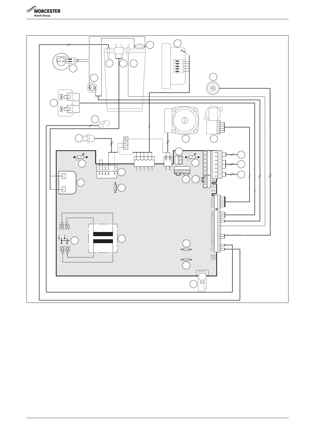
Electrical
6 720 811 922 (2014/07) 27
5.4 ELECTRICAL WIRING DIAGRAM
Fig. 46
[1] Ignition transformer
[2] Flow temperature control
[3] Terminal strip, 230 V AC
[4] Fuse, 2.5 A slow (230 V AC)
[5] Temperature control for hot water
[6] Connection for temperature limiter TB1 (24 V DC)
[7] DHW circulation pump connection, or external heating circuit
pump in a consumer circuit w/o mixer (secondary circuit) Select
service function 5.E
[8] Fuse, 0.5 A slow (5 V DC)
[9] Fuse, 1.6 A slow (24 V DC)
[10] Code plug
[11] Transformer
[12] Main switch
[13] Connecting lead with plug
[14] DHW temperature sensor
[15] Gas valve
[16] Air pressure switch (30 kW only)
[17] Flue gas temperature limiter
[18] Temperature sensor, CH flow
[19] Ignition electrode
[20] Flame monitoring electrode
[21] Temperature limiter for heating block
[22] Fan
[23] Flow turbine
[24] Central heating pump
[25] 3-way valve
[26] Connection for external heating pump (primary circuit)
Select service function 1.E, page 35
[27] Connection for BUS device, e.g. FW100, FR110
[28] Connection for low voltage/volt free connections,
page 33 for more information
[29] Connection for outside temperature sensor
16
9V/25 V
AC 230V
AC 230 V
L
N
Ls
Ns
LR
6
B
B
4
2
1
A
F
6
4
6 720 812 922-02.1O
1
2
3
5
4
8
9
10
11
12
15
14
17
18
19 20
21
22
23
24
25
27
13
28
29
PR
PO NP LP
9
8
7
6
7
LZ
NZ
26