Appliance information
6 720 811 922 (2014/07) 7
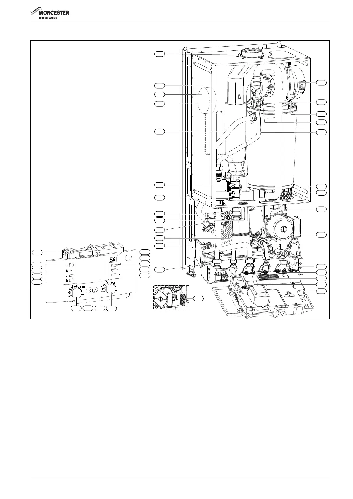
2.4 APPLIANCE LAYOUT
Fig. 2 Main boiler components
[1] Control panel
[2] ON/OFF button
[3] Burner ON indicator light (green)
[4] Service button
[5] Performance test button
[6] CH temperature control
[7] Mains ON/OFF indicator / diagnostic light (blue)
[8] Position for optional plug-in control
[9] DHW temperature control
[10] Key lock
[11] eco button
[12] Fault reset button
[13] System pressure gauge
[14] Display
[15] CH flow pipe to isolating valve
[16] DHW temperature sensor
[17] DHW plate heat exchanger
[18] 3-way diverter valve
[19] Condensate trap
[20] Diverter valve actuator (stepper motor)
[21 ] Gas valve
[22] Inlet pressure test point
[23] CH flow
[24] Flow temperature sensor (NTC)
[25] Air pressure switch (30 kW only)
[26] Expansion vessel
[27] Flue connector
[28] Fan
[29] Combustion air inlet
[30] Maximum safety sensor (NTC)
[31] Electrode assembly
[32] Fan pressure test point
[33] Flue overheat thermostat
[34] Sump assembly
[35] Auto air vent
[36] Pump
[37] Drain point
[38] CH return connection to isolating valve
[39] DCW in connection to isolating valve
[40] Gas pipe from isolating valve
[41] DHW outlet pipe
[42] Safety valve (heating circuit)
27
15
16
1
2
3
4
5
11
12
13
14
6
8
9
7
10
6 720 811 922-01.1O
24
17
23
22
20
19
18
21
25
26
28
29
30
31
32
33
34
35
37
39
40
41
42
36
38