FAULT FINDING
& DIAGRAMS
INSTALLATION & SERVICING INSTRUCTIONS
52
FAULT FINDING
8 716 115 219c (03.2010)
NOTE ; This fault finding information is for
guidance only. Worcester Bosch cannot be held
responsible for costs incurred by persons not
deemed to be competent.
The electronic control system for this boiler
incorporates a blue central indicator. This
normally confirms the permanent mains supply,
but, by flashing during a fault, provides a guide
to the cause as listed.
This fault finding system assumes that the
appliance has been operating normally until the
time of failure (i.e. not a first time installation
error).
Preliminary checks:
Preliminary electrical system checks are the
first electrical checks to be carried out during
a fault finding procedure.
On completion of the Service/Fault finding
task which has required the breaking and
remaking of electrical connections, check:
a) EARTH CONTINUITY
b) SHORT CIRCUIT CHECK
c) POLARITY
d) RESISTANCE TO EARTH.
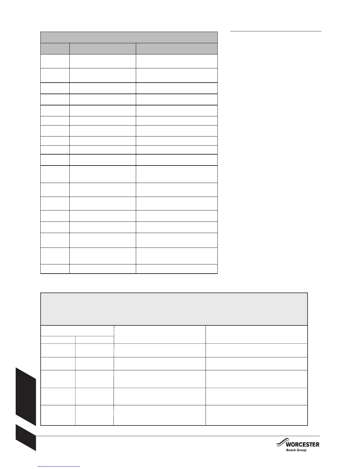
FAULT FINDING
CONDENSATE PUMP - OPERATING LAMPS AND FAULT CONDITIONS
Ready for operation = Steady green light
Fault = Red light
Pump running = Flashing green light
Operating lamps Cause Solution
Green Red
Off Off Mains plug not plugged in Insert plug
Power failure Check mains and fuse
Flashing Flashing Dry-run Pump restarts automatically
(poss. air in pump) after one minute
On Flashing Pump blocked Visual inspection of the pump inlet
in the tank and removal or
rinsing out of dirt/foreign bodies
On On Level exceeds alarm level Pressure hose / non-return valve
blocked (clean or remove kink
if applicable)
Off Flashing Pump blocked and Visual inspection of the pump inlet
alarm level exceeded in the tank and removal or
rinsing out of dirt/foreign bodies
BOILER - FAULTS AND CONDITIONS
Display code: Fault description Check, repair/replace as necessary
A5 Tank NTC defect Check tank NTC sensor and leads,
measure resistance across NTC
(33.5kΩ- 500Ω)
A7 DHW NTC defect Check DHW NTC sensor and leads,
measure resistance across NTC
(33.5kΩ- 500Ω)
A8 EMS communication error Check all electrical connections,
replace control board.
b1 Code plug not detected Insert code plug correctly, test and
replace as necessary.
b2, b3, b4, b5,
b6
Data error Replace control board.
b7 Burner control error Replace control board.
C6 Fan defect Check fan, lead, and connector,
replace as necessary.
D3 External temp limiter Connect terminals 8 & 9 on ST8.
D5 Condensate overflow See condensate pump table.
D6 Internal heat bank overflow Check system pressure, tank, over heat
thermostat, and pump operation
EA Flame not detected Check gas is present, ignition electrodes
and harness, flame sense electrode and
harness, and operation of gas valve.
Replace as necessary.
E2 Primary NTC defect Check primary NTC sensor and leads,
resistance across NTC should be between
36k to 1kΩ
E9 OH stat tripped Check system pressure, over heat thermo-
stat, and pump operation.
Replace as necessary
F0 Internal error Check all electrical connections, replace
board as necessary.
F1 ROM error check Check all electrical connections, replace
board as necessary.
F7 Flame detected after appliance
shut off
Check flame sense electrode and harness,
and control board for signs of water
damage. Replace a s necessary
FA Flame detected after gas shut off Check flame sense electrode and harness,
and control board for signs of water
damage. Check gas valve operation.
Replace a s necessary
Fd Reset button pressed Press reset button again
 Loading...


