6 720 611 400 GB (03.11)
44
Maintenance
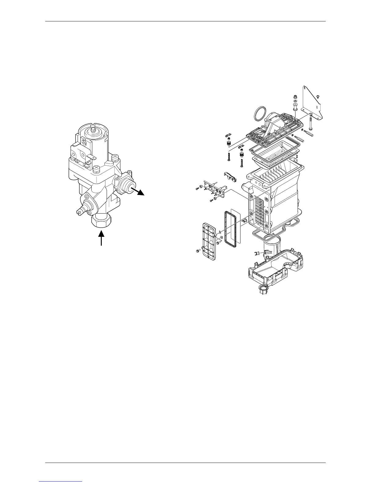
9.3.14 Flow switch
B Shut the mains water inlet valve and drain the domes-
tic hot water circuit.
B Pull-off the connectors from the micro-switch.
B Unscrew the inlet and union connection and remove
the assembly.
B Reset the domestic hot water flow rate on the new
assembly.
Fig. 61
9.3.15 Primary Heat Exchanger
B Drain the appliance.
B Check that the gas supply is turned off.
B Check that the appliance is electrically isolated.
B Remove the fan assembly complete with the gas/air
tube and mixer assembly. Refer to section 9.3.2.
B Remove the burner. Refer to section 9.2.
B Disconnect the sensors. Refer to section 9.3.6.
B Undo the central heating flow union.
B Undo the top connection of the pump. Refer to
fig. 57.
B Undo the grey plastic cap, next to the top pump con-
nection at the base of the heat exchanger.
B Unscrew and remove the condensate trap. Refer to
section 9.2.
B Unscrew and remove the two screws securing the
heat exchanger top bracket to the rear panel.
B Lift up the flue duct, item 271, refer to fig. 2.
B Pull forward from the top and lift the heat exchanger
from the casing.
B Transfer components, as necessary, to the new heat
exchanger.
B Ensure that all the seals are in place and all of the
connections are tight before re-commissioning the
appliance.
Fig. 62
6 720 610 602 - 05.10
INLET
OUTLET
6 720 610 602 - 06.10
 Loading...