6 720 611 400 GB (03.11)
8
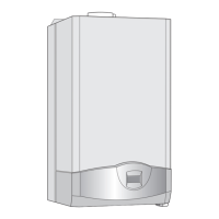
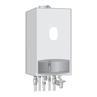
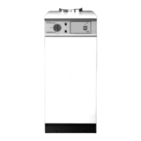
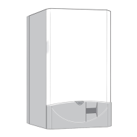
Details of the appliance
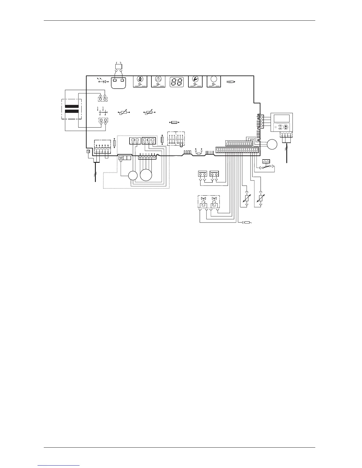
1.8 Electrical wiring diagram
Fig. 4
4.1 Ignition transformer
6 Temperature limiter, heat exchanger
6.1 Hot water NTC sensor
9 Flue gas temperature limiter
18 Pump
32 Flame sensing electrode
33 Ignition electrode
36 Temperature sensor in CH flow
52 Solenoid valve 1
52.1 Solenoid valve 2
56 Gas valve CE 427
61 Reset button
84 Motor, 3-way valve
96 Microswitch, hydraulic switch
135 Master switch
136 Temperature control for CH flow
151 Fuse, slow 2.5 A, AC 230 V
153 Transformer
161 Link
226 Fan
300 Code plug
302 Earth connection
310 Temperature control for hot water
312 Fuse, slow T 1,6 A
313 Fuse, slow T 0,5 A
317 Digital display
328 Terminal block for AC 230 V Mains supply
328.1 Link
363 Indicator lamp for burner
364 Indicator lamp for power supply
365 “Chimney sweep” button
366 Service button
367 ECO button
400 Text display
422 Connecting TR2
6
9
32
33
36
52.1
52
56
61
230 V
135
25 V
230V/AC
153
136
151
12
4
7
89
161
M
226
300
L
NLsNs
328
LR
302
310
312
313
317
363
364
365
366
ECO
367
4.1
328.1
6.1
18
84
96
M
400
4
3
F
M
6 720 610 602 - 02.1O
mains supply
422
o - orange g - green bl - black r - red p - purple
r
r
bl
bl
bl
bl
bl
o
o
o
o
g
g
p
p
p
 Loading...