20. Reinstall the rear access panel with the laser cables within the cut out using the flanged M8
screws.
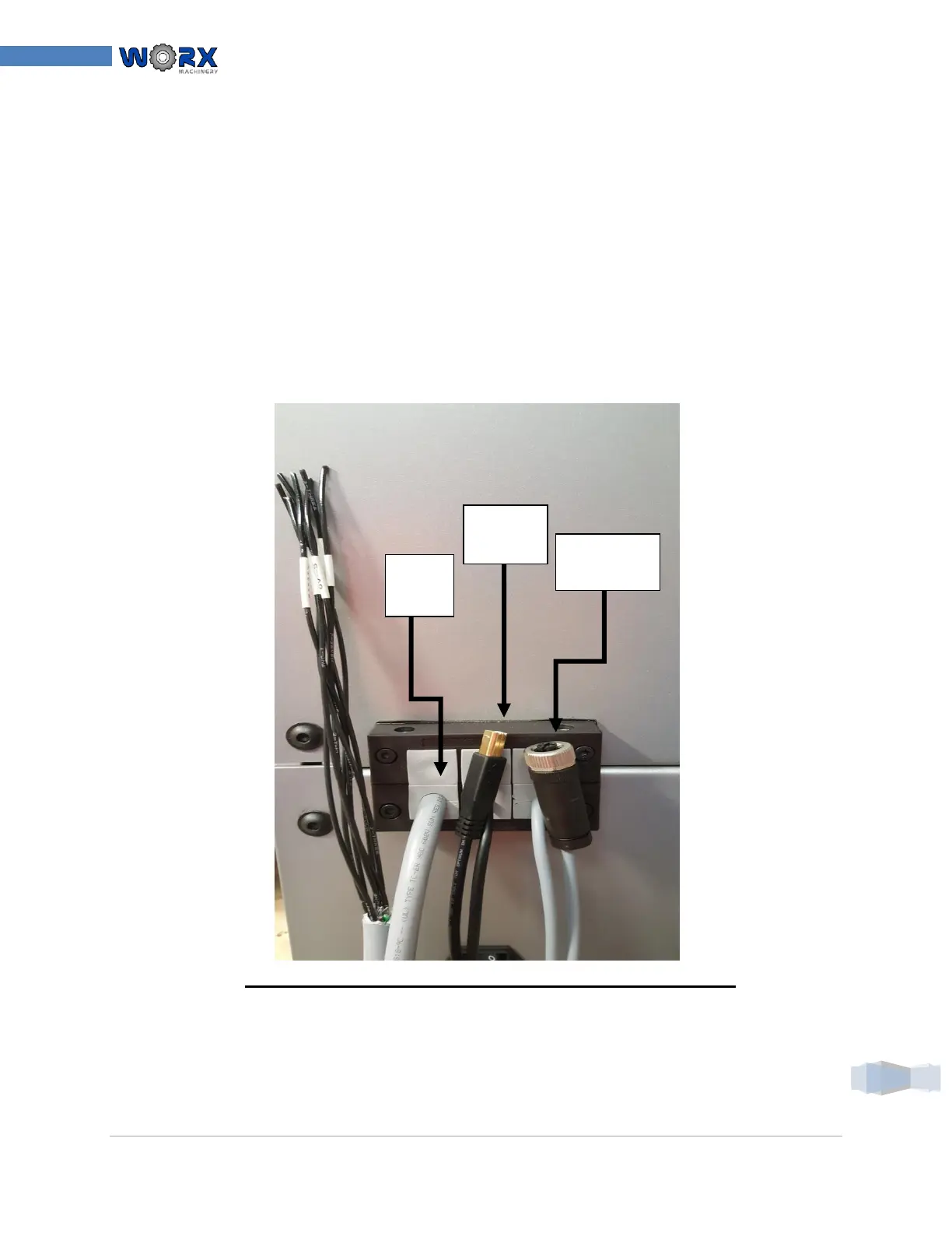
21. Locate the cable entry gland removed from in step 8 and disassemble.
22. Place a single properly sized cable glands around each cable
23. Arrange and load the glands in a manner allowing placement into each half of the black
plastic cable entry housing.
24. Re-install the two long chrome plated ¼”-20 cap screws back into the edge of the cable
entry gland firmly locking the cables into place on the back panel. The screw is to thread into
the nuts on the opposite side of the housing.
25. Place the cable entry gland onto the back of the enclosure using the four SHCS M5 screws
which were taken out in step 8. Secure the cable entry gland housing to the back of the
enclosure.
*NOTE: YOUR APPLICATION MAY LOOK DIFFERENT*
26. Insure all screws have been secured and instructions followed in this section of the
installation.
 Loading...