3.0 OPERATION
42 ©2000 Xantrex Technology Inc.
Front Panel Controls and Indicators (continued)
Over Discharge Protection/AC Transfer Voltage
The Over Discharge Protection/AC Transfer Voltage potentiometer performs two related
functions. When set between the 2 and 5 oclock position (right), both ODP and the AC Transfer
Voltage function simultaneously (see table on next page). When the potentiometer is set between
the 9 and 1 oclock position (left), only the AC Transfer Voltage is functional (ODP is disabled).
Over Discharge Protection (ODP)
When enabled, ODP shuts down the inverter at a specified voltage (low battery cutoff) to
protect the batteries from over discharge damage. The inverter circuitry calculates the lowest
(safe) DC voltage (leaving approximately 20% battery capacity) based on the position the
Battery Type Selector switch and the amount of current drawn by the load. Under no-load
conditions this level is typically between 11.8 and 12.0 VDC (for a 12 volt battery bank).
NOTE: The range of set points between 2 and 5 oclock also determine the low AC Transfer Voltage.
This must be considered when adjusting this potentiometer with ODP enabled (see next page).
NOTE: When ODP is disabled (set points between 9 and 1 oclock), the inverter is programmed to
shut OFF when the batteries reach approximately 8.5 VDC (1.4166 V/cell).
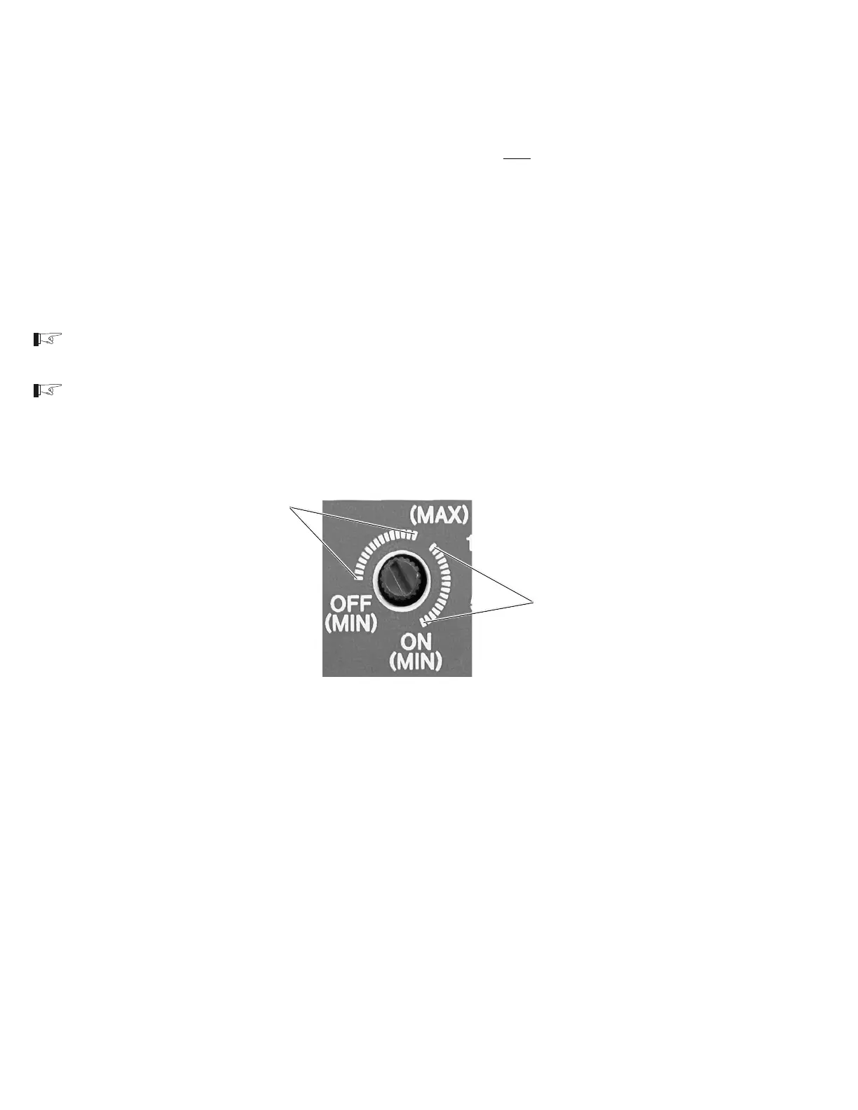
ODP enabled
range
ODP disabled
range
Figure 38
ODP Enabled/Disabled Positions
 Loading...