15
2.0 INSTALLATION
©2000 Xantrex Technology Inc.
Wiring (continued)
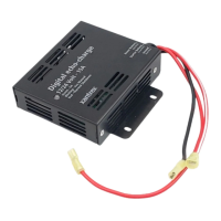
Battery Cable Connections
Battery cables must have crimped (or preferably, soldered and crimped) copper compression
lugs unless aluminum mechanical lugs are used. Soldered connections alone are not acceptable.
High quality, UL-listed battery cables are available from Trace Engineering in an assortment of
lengths: 1-1/2 to 10 feet, and in #2/0 AWG or #4/0 AWG sizes. These cables are color-coded with
pressure crimped, sealed ring terminals.
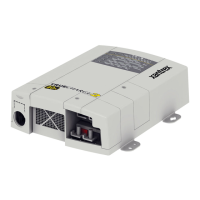
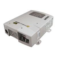
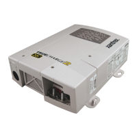
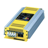
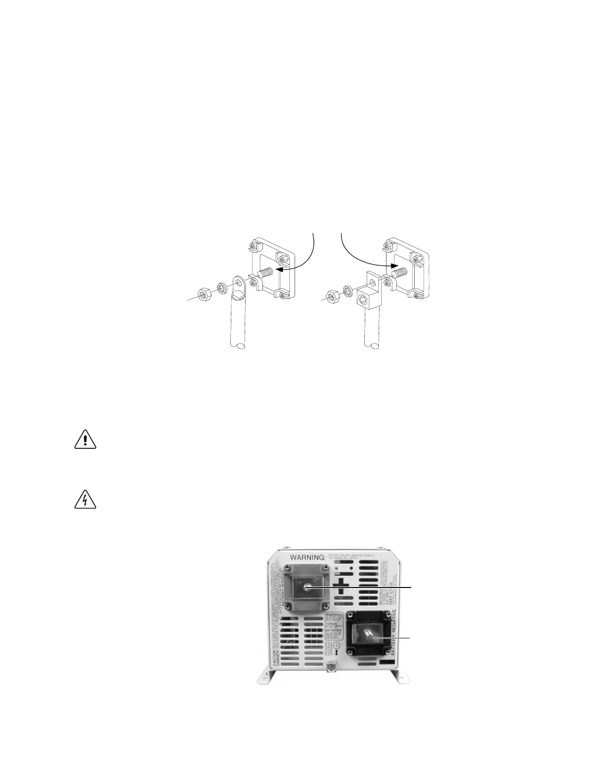
Figure 9 illustrates the proper method to connect the battery cables to the DR Series inverter/
charger terminals.
2/0 Copper Compression Lug 2/0 Aluminum Mechanical Lug
Do not place anything
between battery cable lug
and terminal surface.
Assemble exactly as shown.
Figure 9
Battery Cable Connections to Inverter
CAUTION: THE INVERTER IS NOT REVERSE POLARITY PROTECTED. REVERSING THE
BATTERY POLARITY ON THE DC INPUT CONNECTIONS WILL CAUSE PERMANENT DAMAGE
TO THE INVERTER WHICH IS NOT COVERED UNDER WARRANTY. ALWAYS CHECK
POLARITY BEFORE MAKING CONNECTIONS TO THE INVERTER.
WARNING: ENSURE THE INVERTER IS OFF BEFORE CONNECTING OR DISCONNECTING
THE BATTERY CABLES, AND THAT AC POWER IS DISCONNECTED FROM THE INVERTER
INPUT.
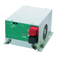
Figure 10
Battery Cable Connections
POSITIVE (+) RED TERMINAL
NEGATIVE (-) BLACK TERMINAL
 Loading...