d
~
a b
e
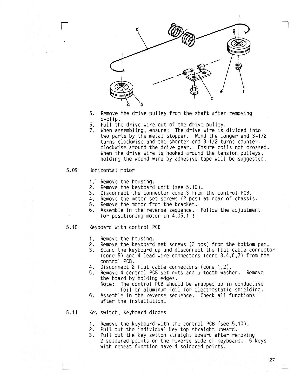
5.
Remove
the drive pulley
from
the shaft
after
removing
c-clip.
6. Pull the drive wire out of the drive pulley.
7.
When
assembling, ensure:
The
drive wire
is
divided into
two
parts
by
the metal stopper.
Wind
the longer
end
3-1/2
turns clockwise
and
the shorter
end
3-1/2 turns counter-
clockwise
around
the drive gear.
Ensure
coils
not crossed.
When
the drive wire is
hooked
around
the tension pulleys,
holding the
wound
wire
by
adhesive tape will
be
suggested.
5.09 Horizontal
motor
1.
Remove
the housing.
2.
Remove
the keyboard unit (see 5.10).
3. Disconnect the connector
cone
3
from
the control
PCB.
4.
Remove
the
motor
set
screws
(2
pcs) at
rear
of
chassis.
5.
Remove
the
motor
from
the bracket.
6.
Assemble
in
the reverse sequence.
Follow
the adjustment
for positioning
motor
in 4.05.1 !
5.10
Keyboard
with control
PCB
1.
Remove
the housing.
2.
Remove
the keyboard
set
screws
(2
pcs)
from
the
bottom
pan.
3. Stand the keyboard
up
and
disconnect the
flat
cable connector
(cone
5)
and
4 lead wire connectors
(cone
3,4,6,7)
from
the
control
PCB.
4. Disconnect 2
flat
cable connectors
(cone
1,2).
5.
Remove
4 control
PCB
set
nuts
and
a tooth washer.
Remove
the
board
by
holding edges.
Note:
The
control
PCB
should
be
wrapped
up
in
conductive
foil
or
aluminum
foil
for
electrostatic
shielding.
6.
Assemble
in
the reverse sequence.
Check
all
functions
after
the
installation.
5.11
Key
switch,
Keyboard
diodes
L
1.
Remove
the keyboard with the control
PCB
(see 5.10).
2. Pull out the individual
key
top
straight
upward.
3. Pull out the
key
switch
straight
upward
after
removing
2 soldered points
on
the reverse side of keyboard. 5
keys
with repeat function
have
4 soldered points.
27