10 www.xilinx.com VC7203 IBERT Getting Started Guide
UG847 (v3.0) July 10, 2013
Chapter 1: VC7203 IBERT Getting Started Guide
it is not already inserted (see Figure 1-4).
Note:
Figure 1-4 is for reference only and might not reflect the current version of the connector.
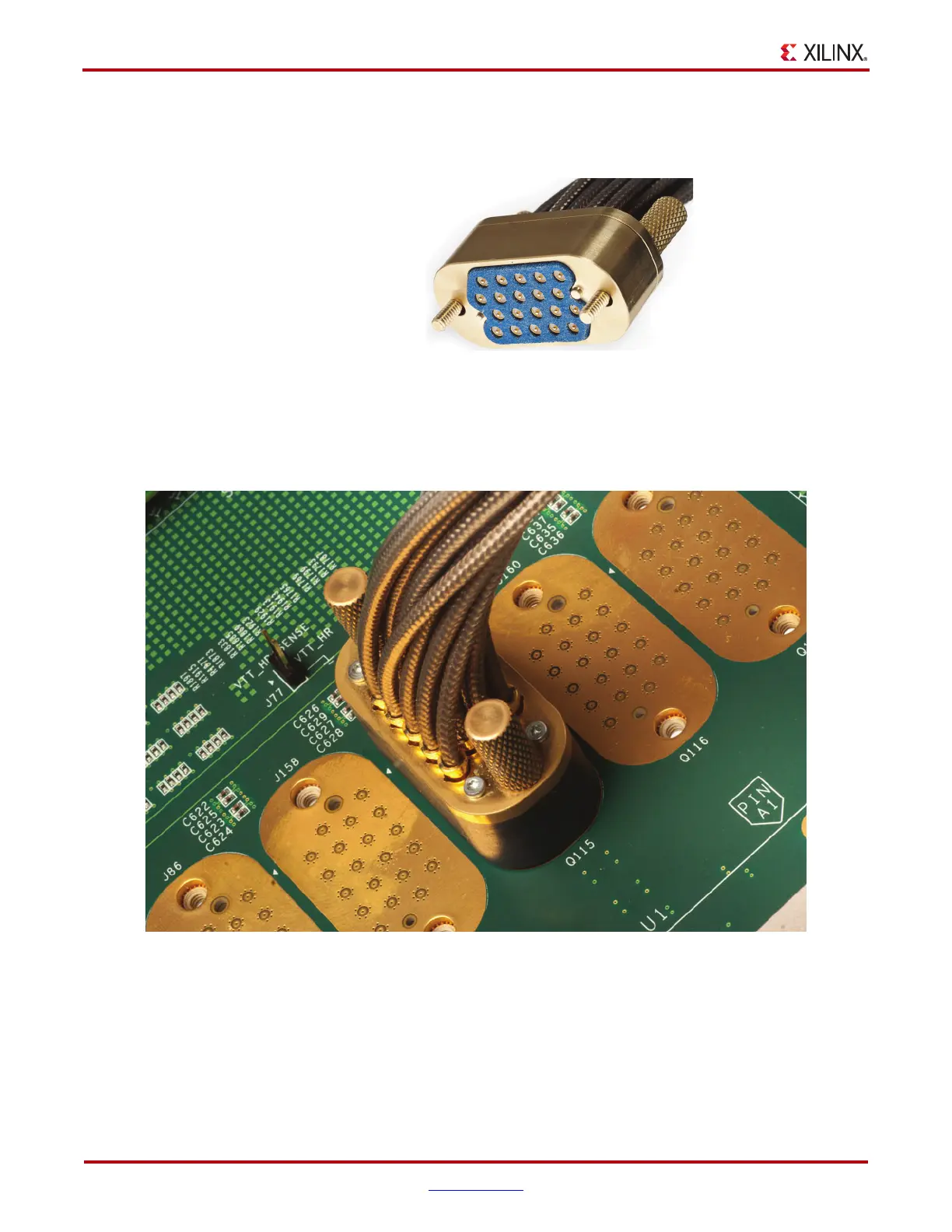
Attach the Samtec BullsEye connector to GTX Quad 115 (Figure 1-5), aligning the two
indexing pins on the bottom of the connector with the guide holes on the board. Hold the
connector flush with the board and fasten it by tightening the two captive screws.
GTX Transceiver Clock Connections
See Figure 1-2, page 9 to identify the P and N coax cables that are connected to the CLK1
reference clock inputs. Connect these cables to the SuperClock-2 module as follows:
• CLK1_P coax cable → SMA connector J5 (CLKOUT1_P) on the SuperClock-2 module
X-Ref Target - Figure 1-4
Figure 1-4: BullsEye Connector with Elastomer Seal
UG847_c1_04_1013112
X-Ref Target - Figure 1-5
Figure 1-5: BullsEye Connector Attached to Quad 115

 Loading...
