Note: the upper computer can set the subdivision and other functions. When SW1-SW4 are all on, the upper
computer can set the subdivision, please power on again after setting. Other switch status is subject to dialing
setting.
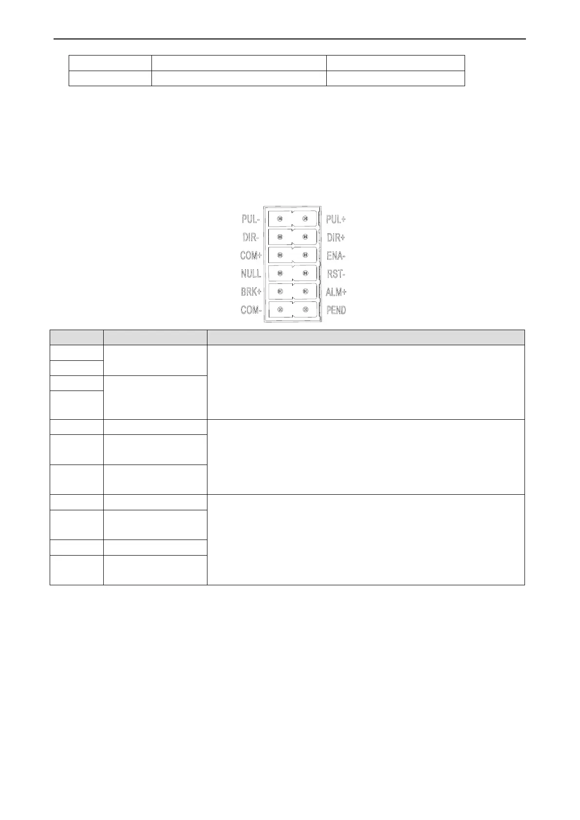
3-3. Control signal interface
3-3-1. Function
The 5/24 VDC pulse input signal can be selected by dialing code, and the
pulse edge can be changed through the upper computer according to the
demand. The rising edge is valid by default.
(!!! Note: the input of 24V signal will damage the input terminal when
5 V is selected.)
Two channels of input signal, support 24V signal
Alarm clearing input
signal
Input signal common
terminal
Three output signals, maximum saturation output 50 mA, maximum 24
VDC. Pend+/Z terminal default is in place signal, the customer can
modify the in place signal to Z signal through the upper computer
according to the demand.
Output signal
common terminal
 Loading...