Do you have a question about the Xinje ZG3 Series and is the answer not in the manual?
Describes the manual's content, scope, and intended audience.
Lists available support channels and company contact information.
Highlights critical precautions for safe operation and product protection.
Lists hazardous situations requiring extreme caution to prevent injury or damage.
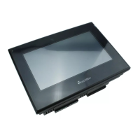
Details the key features and specifications of the ZG3 series integrated PLC&HMI.
Explains the system for naming different product models based on series, type, and points.
Lists electrical parameters such as input voltage, power failure time, and insulation resistance.
Details the technical specifications of the Human-Machine Interface, including screen and life.
Outlines the technical details of the PLC functionality, including I/O points and memory.
Describes capabilities for high-speed counting operations and frequency modes.
Details features related to generating high-speed pulse signals.
Explains how external events can trigger interruptions and associated pointers.
Illustrates the physical layout, power supply, and I/O terminal connections.
Describes the download (COM0) and communication (RS485) ports.
Explains the USB port functionality for HMI program downloads.
Provides detailed measurements for the product, including overall and installation dimensions.
Details electrical parameters for input signals, including voltage, current, and response time.
Lists electrical ratings for relay outputs, covering load capacity and response time.
Details parameters for transistor outputs, including high-speed pulse capabilities.
Recommends programming software and lists basic PLC instructions.
Details application, data transmission, calculation, and conversion instructions.
Provides an overview of software components, their ranges, and points.
Guide to TouchWin software, HMI selection, and PLC communication setup.
Describes initial status bits and clock-related registers (SM0-SM14).
Registers for managing high-speed pulse outputs and related flags (SM1000-SM1190).
Registers for monitoring system errors and communication status (SM400-SM413, SM130-SM1319).
Registers for storing time and date information (SD010-SD019).
Registers for high-speed counting operations and status (SD100-SD109).
Registers related to high-speed pulse data and error messages (SD1004-SD1029).
Registers for input filtering, watchdog, and terminal mapping (SFD0*-SFD12*).
Registers for HSC frequency, selection, and CAM function (SFD320-SFD332).
Configuration settings for COM1 and COM2 communication modes and formats.
Settings for pulse output parameters, including number, amount, and direction.
Parameters for max speed limiting, starting, ending speeds, and curve acceleration.
Settings for mechanical origin, limits, and terminal configurations.
| Brand | Xinje |
|---|---|
| Model | ZG3 Series |
| Category | Recording Equipment |
| Language | English |