Rev.: 20110111
Platform: XK09
Firmware: CHRYSLER
© 2011 Directed Electronics. All rights reserved.
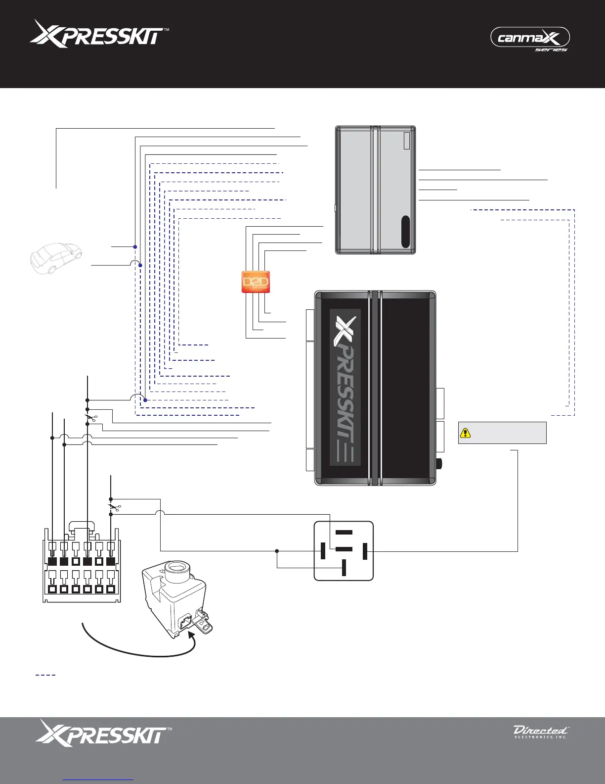
Vehicle Canbus Integration System
The Mobile Integration Systems
Installation Type 1
Page 3
** If the kit you have purchased does not include a 4-pin black harness to accommodate the Relay wire, use a D2D or relay pack harness.
* The Tach wire is an optional connection required on some remote starters not supporting tach signal in D2D.
Not required in D2D mode.
Programming Button
4
4
4
20
2
XK09
1: (+) 12 V
2: RX
3: (-) Ground
4: TX
2: Green: (-) Door/Trunk Sense Output
1: Violet/White: (AC) Tach Output*
Remote
Starter
1: Red/Blue: Relay**
2: -
3: -
3: -
4: -
4: -
(AC) Tach Input*
(-) Door/Trunk Sense Input
Parking Lights
(-) Neutral Safety (DEI platforms only)
(-) Hood
(-) Door Status (1* only)
15: Yellow
17: Orange
9: Red: (+) 12 V
1: Blue/White: (-) GWR (status)
2: Violet/Black: (-) Aux2 Left Sliding Door
3: Light Green: (-) Lock Input
4: White/Violet: (-) Aux1 Right Sliding Door
5: Blue: (-) Unlock Input
6: Red/White: (-) Trunk Input
7: Violet: (+) Starter Input
8: Pink: (+) Ignition Input
(+) 12 V
RX
(-) Ground
(-) Ground
Rearm (RAP OFF)
TX
(+) 12 V
(+) Ignition Output
(+) Starter Output
(-) Trunk Output
(-) Unlock Output
(-) Aux2 Right Sliding Door
(-) Aux1 Left Sliding Door
(-) Lock Output
(-) GWR (status)
10: Black: (-) Ground
19: Tan: HSCAN Low
20: Tan/Black: HSCAN High
The Relay wire must be
connected to the first pin on
the left of the connector.
(+) 12 V
(-) Ground
(-) Driver Door Pin
(+) Ignition
(+) 12 V (Batt.)
CAN High
CAN Low
30
86
85
87
87a
1
6
12
7
Facing view
Behind Ignition Switch
Ignition
Barrel