DS8000 Operator’s Manual Page 22
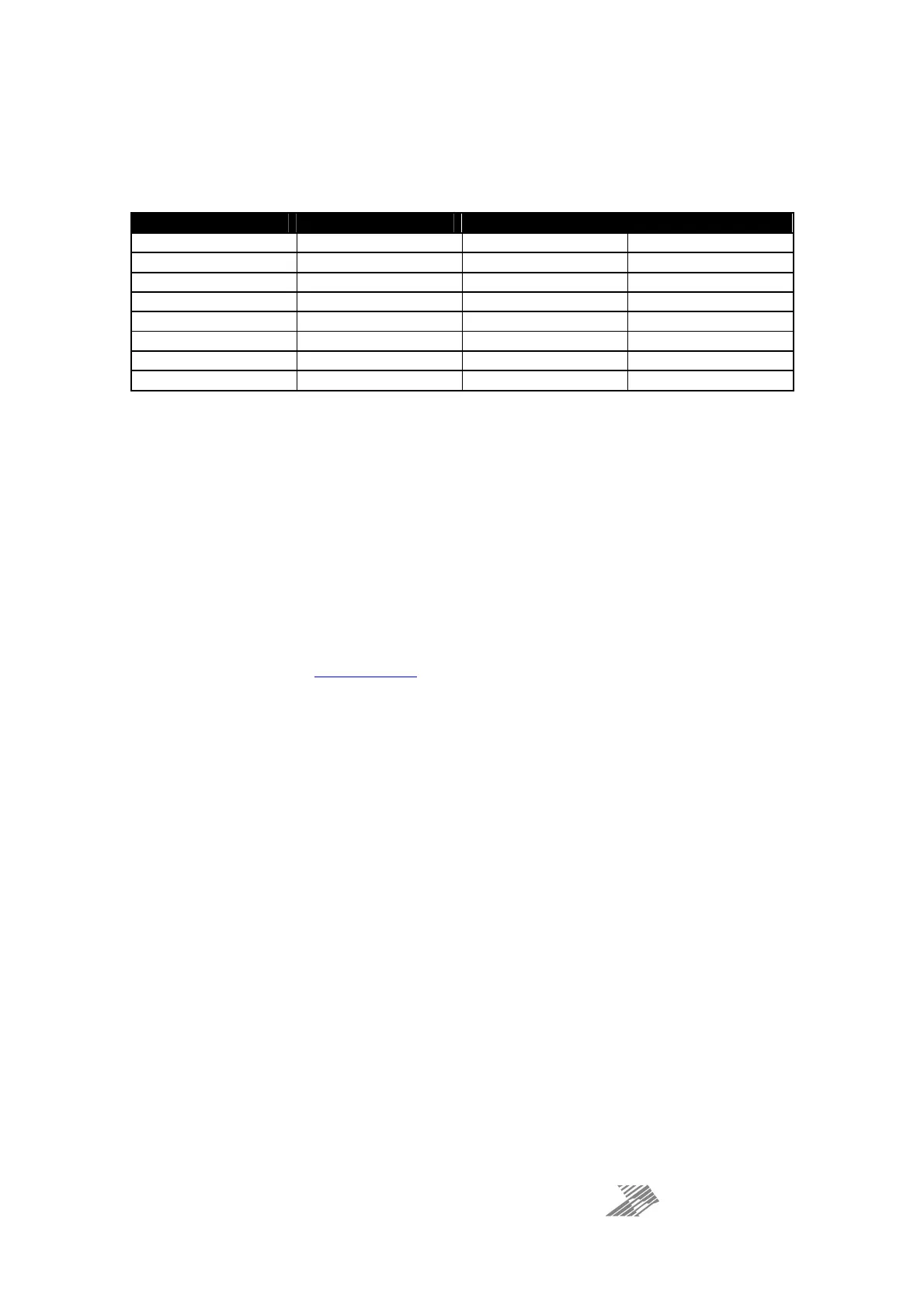
AES Outputs: Pinout and Drive Capabilities
Two transformer balanced, isolated sets of AES outputs are available on the DB25 connector.
The wiring follows the TASCAM convention, as shown in the table below:
Output Pair Hot Cold Ground
A1
A1A1
A1
(Chs 1
(Chs 1(Chs 1
(Chs 1&2)
&2)&2)
&2)
24 12 25
A2
A2A2
A2
(Chs
(Chs (Chs
(Chs 3
33
3&
&&
&4
44
4)
))
)
10 23 11
A3
A3A3
A3
(Chs
(Chs (Chs
(Chs 5&6
5&65&6
5&6)
))
)
21 9 22
A4
A4A4
A4
(Chs 7&8
(Chs 7&8(Chs 7&8
(Chs 7&8)
))
)
7 20 8
B1 (Chs 1&2)
B1 (Chs 1&2)B1 (Chs 1&2)
B1 (Chs 1&2)
18 6 19
B2 (Chs 3&4)
B2 (Chs 3&4)B2 (Chs 3&4)
B2 (Chs 3&4)
4 17 5
B3 (Chs 5&6)
B3 (Chs 5&6)B3 (Chs 5&6)
B3 (Chs 5&6)
15 3 16
B4 (Chs 7&8)
B4 (Chs 7&8)B4 (Chs 7&8)
B4 (Chs 7&8)
1 14 2
The DS8000’s digital outputs utilise industry standard drivers and circuitry to ensure that the
performance of the digital outputs is as widely compatible as possible with other professional
equipment.
The pairs of outputs will drive into 110R standard loads, tested up to cable distances of 100
metres.
Please ensure that high quality AES specified cable is used for all connections — the use of
poor cables on one AES pair may have an adverse effect on the other pair (incorrect
terminations/loads on A1 may have an affect B1 and so on).
If you are unsure about what type of cable to use, please feel free to give us a call to discuss
your application or email tech@xta.co.uk.