VESDA VLF-500-UL 7Ed Product Guide VESDA
8 www.xtralis.com
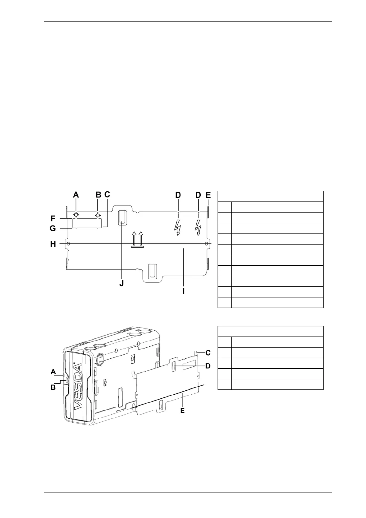
2.3.1 Installation Procedure
Cut the air inlet pipe and exhaust pipe (if used) at 90°, and to the same length (for normal and inverted
mounting). Remove all rough edges. This is critical to obtain an air tight seal with the smoke detector.
1. Position the air inlet centerline mark (A) of the mounting bracket against the end of the air inlet pipe.
Refer to Figure 2-4 below.
2. In the cut out section of the mounting bracket mark a line across the top of the cut out if metric size
pipe is used or mark a line across the bottom of the cut out if Imperial size pipe is used.
3. Slide the mounting bracket down (up for inverted mounting) until the top of the bracket aligns with the
marked line.
4. Mark off and drill the 2 bracket mounting holes (H).
5. Screw the bracket to the wall.
6. Hook the smoke detector onto the mounting bracket tabs and pull it down into place.
7. Use the two M4 x 20 mm locking screws provided and screw them into the screw holes on the left and
right side of the detector. See the items marked (F) in Figure 2-4 below.
8. The air sampling pipe can now be attached and power connected.
(Refer to Section 2.7 on page 12 for connection information).
For inverted installation, to mark off the location of the mounting holes, follow steps 1 – 4 with the mounting
bracket inverted to that shown in Figure 2-4 below. Also refer to Section 2.3.2 on page 9.
Legend
A Air inlet port centerline
B Exhaust air port centerline
C Cutout
D Cable entry centerlines
E Mounting tab
F Metric OD 25 mm pipe mark
G Imperial IPS ¾ in. pipe mark
H Bracket mounting holes
I Centerline of detector
J Anti-tamper clip
Figure 2-4: Mounting bracket orientation for upright and inverted mounting
Legend
A Security tab
B Finger clip
C Mounting tab
D Anti-tamper clip
E Centerline of detector
Figure 2-5: Mounting bracket rear view
 Loading...