Do you have a question about the Xtrails VESDA VLF-500-UL and is the answer not in the manual?
Critical safety precautions for installation, configuration, and use of the product.
Statement regarding the document's content accuracy and manufacturer's right to change specifications.
Explanation of typographic conventions and icons used in the document.
Contact details for Xtralis support in different regions.
Details on the equipment's compliance with FCC rules for digital devices.
Information on the product's compliance with FDA regulations for laser products.
Configuration requirements for UL 268 Ed7 standard compliance, including alarm thresholds.
Using ASPIRE software for pipe network analysis and compliance to standards.
Requirements for UL installations, including ASPIRE software for pipe network design.
Importance of taking electrostatic discharge precautions before opening the detector.
Step-by-step procedure for removing the detector's fascia.
Detailed dimensions of the VESDA VLF detector and its mounting bracket.
Guidelines for mounting the VESDA VLF detector in various orientations.
Instructions for installing the detector, including mounting bracket placement.
Step-by-step procedure for mounting the detector and bracket.
Procedure to invert the user interface display for inverted mounting applications.
Step-by-step instructions for safely removing the detector from its mounting.
Guidelines for connecting air inlet and exhaust pipes to the detector.
Information on detector cabling requirements and terminal block layout.
Reserved terminals for future use on the detector's terminal block.
Details on power supply voltage, consumption, and connection terminals.
Description of relay terminals (12-20) and their functions for alarm/fault signals.
Typical wiring diagram for connecting VESDA detectors to a conventional fire alarm panel.
General procedures and checks before commissioning the detector.
Initiating and understanding the AutoLearn Smoke process for threshold setting.
Initiating and understanding the AutoLearn Flow process for air flow normalization.
Information on using Xtralis VSC software for detector configuration.
Procedure for conducting a smoke test to verify pipe network integrity.
List of key features and functionalities of the VESDA VLF detector.
Detailed description of the detector's display, logging, and sensing capabilities.
Common applications and environments where the VESDA VLF detector can be used.
Identification of ports, display, and deflector on the detector's front panel.
Location and function of controls and indicators behind the service access door.
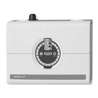
How the Smoke Dial displays smoke levels and incident information.
How to use the Instant Fault Finder function to diagnose faults.
Table detailing fault types, explanations, and recommended actions for diagnosis.
Details on supply voltage, power consumption, and current.
Information on detector dimensions, weight, IP rating, and mounting.
Environmental conditions for detector operation, including temperature and humidity.
Specifications for air inlet pipe, single pipe, branched pipe, and return air sampling.
The maximum area that the VESDA VLF-500-UL can monitor.
Information on cable access and terminal specifications for field wiring.
Details on available interfaces such as relays, GPI, and RS232.
Defined ranges for alert, action, fire 1, and fire 2 alarm levels.
Description of the various indicators on the detector's display.
Details on the event log capacity and types of events recorded.
Parameters and default periods for AutoLearn Smoke and Flow processes.
Information on using a reference smoke level source for networked detectors.
Part numbers and descriptions for the VESDA VLF detector and accessories.
Continuous monitoring and health checks performed by the VESDA VLF.
Step-by-step guide for replacing the air filter cartridge and resetting the detector.
Step-by-step guide for replacing the detector's aspirator.
The main form for documenting the commissioning of each customer site.
Settings for button lockout, smoke test, reset, isolate, and relay connections.
Configuration options for fault, action, and fire 1 relays.
Settings for the VESDAnet Interface Card, including preferred port and loop status.
Configuration options for the VESDAnet Multi-Function Relay Card.
Information on remote displays, relay cards, AOM, and SRM assigned to the detector.
Fields for inputting ASPIRE data such as sensitivity, balance, and flow rate.
| Brand | Xtrails |
|---|---|
| Model | VESDA VLF-500-UL |
| Category | Security System |
| Language | English |