VESDA-EVES-A10-P Product Guide
42 www.xtralis.com
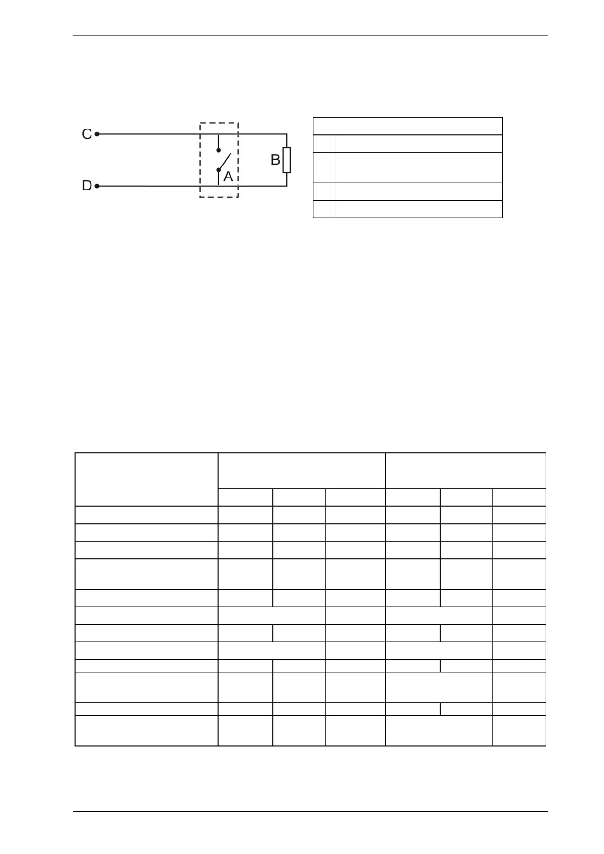
4.3.11 Typical Wiring for Monitored GPI for PSU Monitoring
The diagram below shows the correct way to configure power supply monitoring. It also shows where an End
Of Line (EOL) resistor is correctly installed. Refer to Section 4.3.8 on page 40 for further information.
Legend
A External device (1 to N)
B End of Line Resistor at device end of
wiring
C GPI Pin 1
D GPI Pin 2
Figure4-39: Power Supply Connection Diagram
4.3.12 Specify Backup Battery
In the event of a mains power supply disruption, the VES-A10-P detector runs on a backup battery located in
the external power supply (the power supply must be compliant with local fire protection codes and
standards). The size of the battery is determined by:
l local codes and standards
l the total power required by the system
l back up time required
l allowance for reduction in capacity with age
l expected temperature variations
Note: It is recommended that batteries be inspected and changed as per manufacturer’s specifications or
as per local codes and standards.
To facilitate the calculation of the backup battery size, a Battery Calculation Sheet is included below.
Equipment Normal loads@ 24 V DC
(Backlight off)
Full alarm load @ 24 V DC
(Backlight on)
Load (A) Qty Total Load (A) Qty Total
Detector set to Fan Speed 1 0.36 0.39
Detector set to Fan Speed 5 0.44 0.45
Detector set to Fan Speed 10 0.64 0.64
Other 24V Loads Total
(A)
Total
(A)
X X
Normal Hours Alarm Hours
=
Normal Capacity Alarm Capacity
Total Capacity =
Normal + Alarm
Multiply by battery
factor X1.25
Table4-3: Calculating the size of backup battery