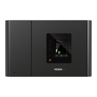
VESDA VFT Product Guide
VESDA by Xtralis
16 www.xtralis.com
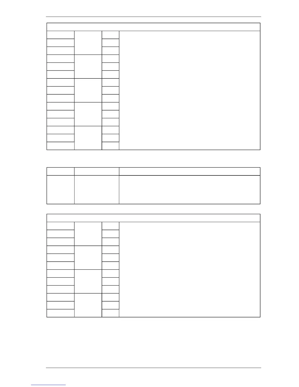
CN7: Output Relay Interface
1 FIRE 2 C Requires 7 x 0.2 - 6 A (24 AWG) cable
Notes:
l Maximum relay contact rating is 2 A @ 30 VDC.
l Refer to Section 5.4.1 for details of individual sector relay
options.
l For use in UL/ULC Fire Alarm Application, refer to
AppendixFItem2.
2 NC
3 NO
4 FIRE 1 C
5 NC
6 NO
7 ACTION C
8 NC
9 NO
10 ALERT C
11 NC
12 NO
13 FAULT C
14 NC
15 NO
Note: Connection CN14 is only used for special applications.
Table 3-3: Connections to Processor Board
Connector Pin Description Description
8-pin RJ45 Standard Ethernet
connections
Standard Ethernet cable.
Notes:
l Refer to Section D.4 for further details.
l Not tested for UL/ULC Fire Alarm connection application.
Table 3-4: Connections from 4 Channel Relay Board (Optional Module)
Output Relay Interface (i606)
1 RELAY 1 C Requires 7 x 0.2 - 6 A (24 AWG) cable.
Notes:
l Maximum relay contact rating is 2 A @ 30 VDC.
l Refer to Section 5.4.1 for full operational details.
2 NC
3 NO
4 RELAY 2 C
5 NC
6 NO
7 RELAY 3 C
8 NC
9 NO
10 RELAY 4 C
11 NC
12 NO
 Loading...