VESDA by Xtralis
VESDA VFT Product Guide
www.xtralis.com 17
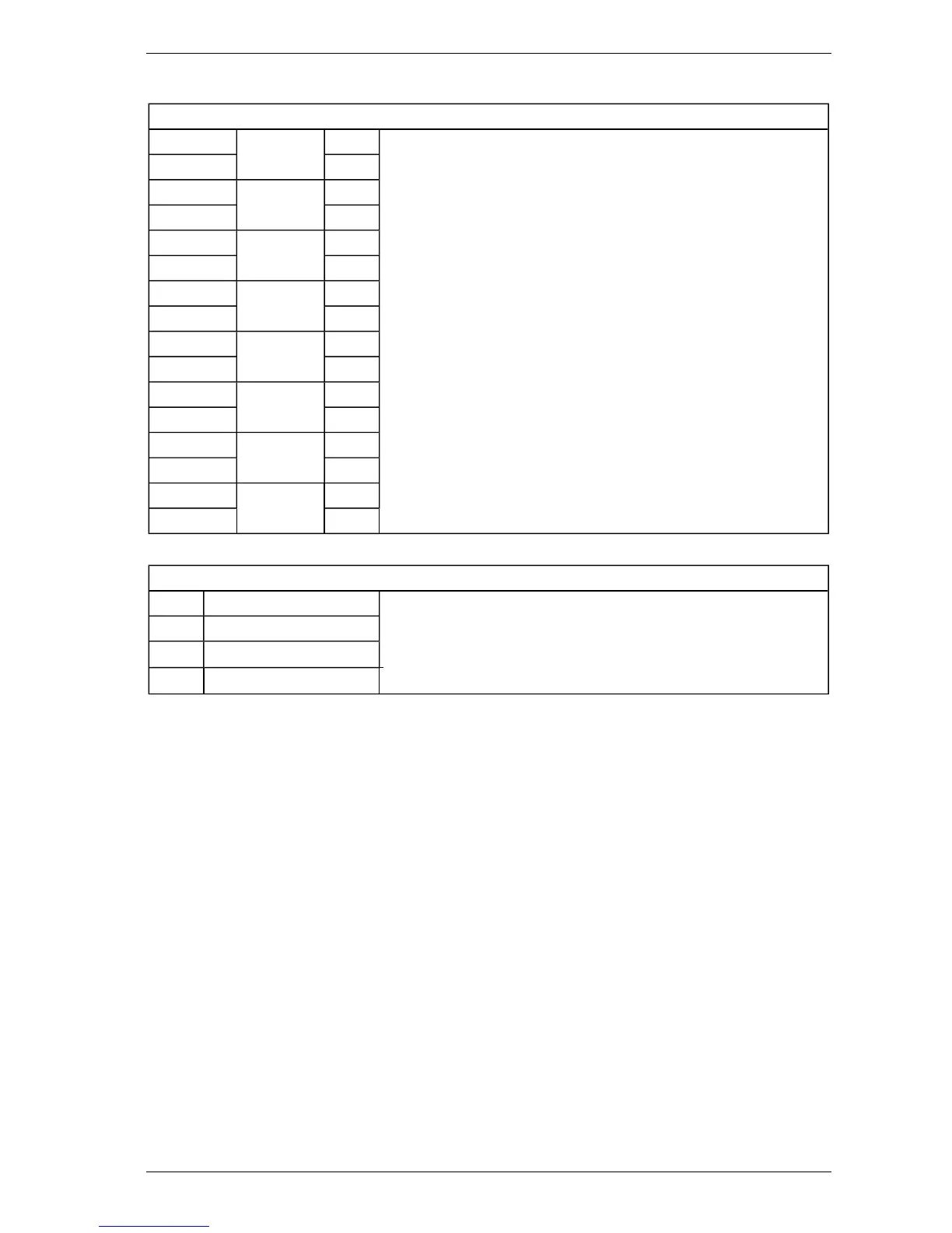
Table 3-5: Connections from Current Output Board (Optional Module)
Output Connections (i624)
1 Output 1 + All outputs have the following specifications:
l 20 VDC max.
l 4 - 20 mA output current (optional 0 - 20 mA)
l 7 x 0.2 - 6 A (24 AWG) cable
Refer to Section 5.4.2 for full operational details
2 -
3 Output 2 +
4 -
5 Output 3 +
6 -
7 Output 4 +
8 -
9 Output 5 +
10 -
11 Output 6 +
12 -
13 Output 7 +
14 -
15 Output 8 +
16 -
Table 3-6: Connections to Remote Panel (Optional) - from i620 Control Board
RS485 Remote Control Data
1 +24 VDC (Supply Out) Belden 9842 (24 AWG) cable (or equivalent)
Notes:
l Ensure that a jumper link is fitted across pins 1-2 of CN 6.
l Refer to Sections 3.4 and D.4 for further details.
2 0 V (Supply Common)
3 RS485 +
4 RS485 -
Notes:
l Refer to Section 3.4 for details.
l Not tested for UL/ULC Fire Alarm connection application.
 Loading...