VESDA by Xtralis VESDAVLSProduct Guide
www.xtralis.com 7
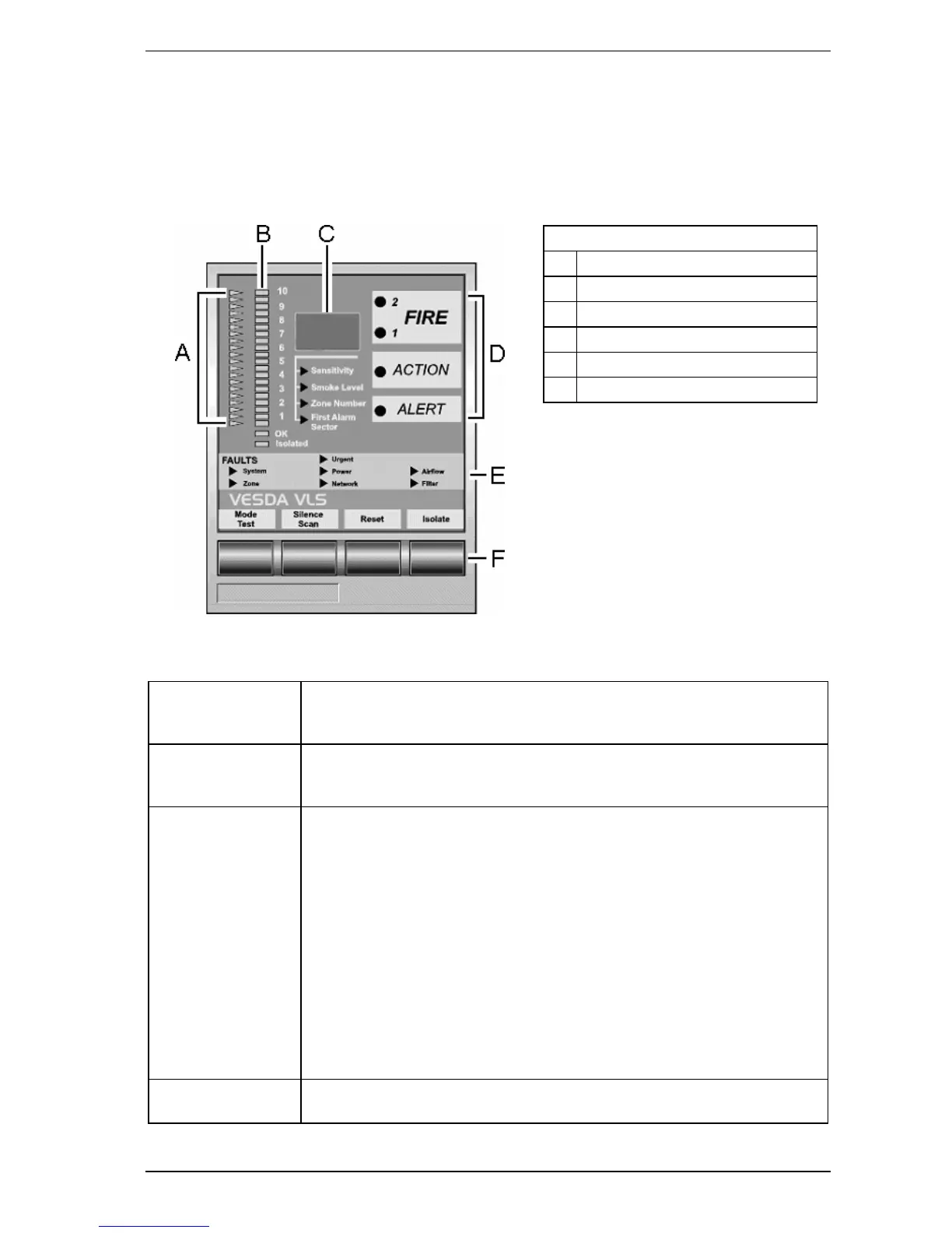
2.2.1 Display Module
The VESDA VLS Display Module is mounted either on the detector front cover or at a remote location in a
remote mounting box or a 19" subrack. It provides a visual representation of the smoke levels and the four
alarm stages for the assigned detector. An array of fault LEDs light up in different configurations to report
Urgent, Minor, Zone and System faults. Up to 20 Display Modules can be assigned to one detector, however
the Display Module can be configured to report the status of only one detector at a time.
Legend
A Threshold Indicators
B Bar graph
C Numerical Display
D Alarm Level LEDs
E Fault LEDs
F Push Button Keys
Figure 2-3: VESDA VLS Display Module
OK LED The OK LED stays lit during normal operation indicating the unit is functioning
normally. When this LED is off a warning beep sounds, indicating a Fault condition
is active.
Isolate LED This LED is lit when the detector is Isolated and relays are de-activated disabling
alarm outputs of the detector. The display can be programmed to beep every 60
seconds.
Alarm Levels ALERT: When lit this LED indicates that the smoke level is above the alert
threshold. This means the detector has identified very early stages of a fire
condition and/or that the smoke level in the area is above normal.
ACTION: When lit this LED indicates that the detected smoke level has passed
the threshold value fixed for Action, but is not intended to initiate a general fire
alarm response procedure.
FIRE 1: When lit this LED indicates that the detected smoke level is above the
threshold value set to initiate a general fire alarm response procedure. This
indicates a fire may be imminent or is in progress. When interfaced with a Fire
Alarm Control Panel (FACP) it can generate an automatic fire alarm.
FIRE 2: When lit this LED indicates a fire is in progress. The detector can be
interfaced with an FACP to activate automatic suppression systems and
evacuation procedures.
Bar Graph The Bar graph is a 20 step indicator where each indicator represents an increase in
the detected level of smoke, relative to the preset fire alarm level.
Table 2-1: Remote Display Module
 Loading...


