VESDA by Xtralis VESDAVLSProduct Guide
www.xtralis.com 27
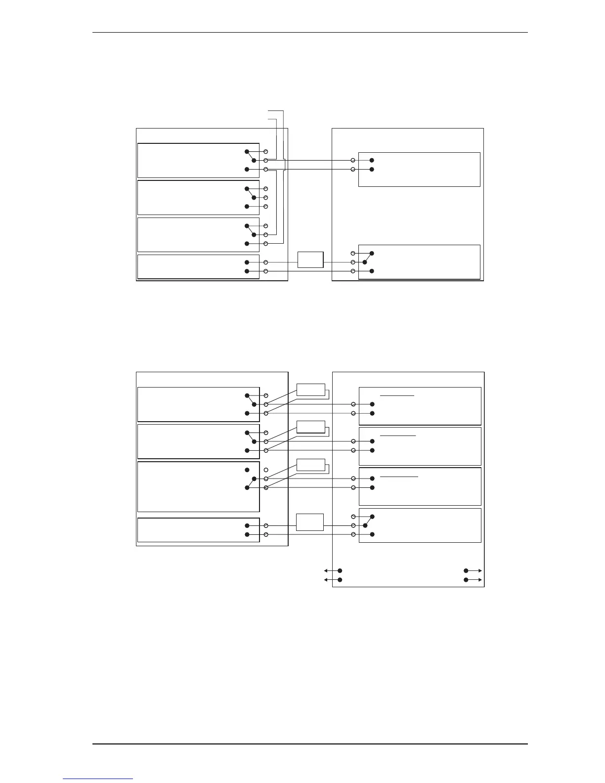
6.1.3 Typical Wiring To Fire Alarm Control Panel (FACP)
The diagram below shows the correct way to wire VESDA detectors to a conventional fire alarm control panel
(FACP). It also shows where an End Of Line (EOL) resistor is correctly installed.
Normally Closed (NC)
Normally Closed (NC)
ACTION Common (C)
FAULT Common (C)
GPI
Detector
(NC)
(NO)
Input
Short = Fire
Open = Fault
To next detector
or End of Line resistor (EOL)
Fire Panel (FACP)
+
-
5-30VDC
+
-
FIRE 1 Common (C)
Normally Open (NO)
Normally Open (NO)
Normally Closed (NC)
Normally Open (NO)
(Set to reset)
Reset (C)
The relay is
energised
on reset.
Figure 6-6: Typical wiring to a fire panel with EOL
6.1.4 Wiring To an Addressable Loop Module
This wiring example is for wiring VESDA detectors to a typical Address Loop module 3 input 1 output. These
are example drawings. Refer to the appropriate product manual for the exact wiring details of the third party
equipment.
FIRE 1 Common (C)
ACTION Common (C)
FAULT Common (C)
Detector
(NC)
(NO)
Fire Input
Short = Fire
To Next Detector
EOL* = Normal
Short = Fire
Fault Input
EOL* = Normal
EOL*
EOL*
EOL*
*EOL: End of Line Resistor
Relay shown energized which
is the no-fault condition
+
-
5-30VDC
+
-
Normally Closed (NC)
Normally Open (NO)
Normally Closed (NC)
Normally Open (NC)
Normally Closed (NC)
Normally Open (NO)
GPI
(Set to “Reset”)
To FACP
3 Inputs 1 Output Loop Module
Open = Wiring Fault
Pre Alarm
Open = Wiring Fault
Short = Detector Fault
Open = Wiring Fault
The relay is
energised
on reset
Reset (C)
EOL* = Normal
Figure 6-7: Addressable Loop Module with EOL

 Loading...