VESDA by Xtralis VESDAVLSProduct Guide
www.xtralis.com 39
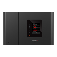
Legend
G 2 Manifold retaining screws
H 4 Retaining tabs
Figure 11-3: Remove the chassis
9. The manifold is held in place by four tabs (H). Use a flat head screw driver to lever out the tabs near the
head termination card, and lift up that end of the manifold. While holding the manifold up, use the screw
driver to lever out the other two tabs. This is a tight fit. As you lift out the manifold note that the flow
sensor and scanner cables disappear through a hole in the manifold. Once the manifold has been lifted
out you can see that these cables are still connected to the flow sensor board on the air inlet pipe
manifold.
Note: The chassis consists of the detection chamber, head processor card and flow sensors. These are
factory calibrated as a matched set and must not be separated. Separating the set and replacing it
with components from another VESDA VLS will cause the detector to malfunction. This will require
the chassis to be returned to the factory.
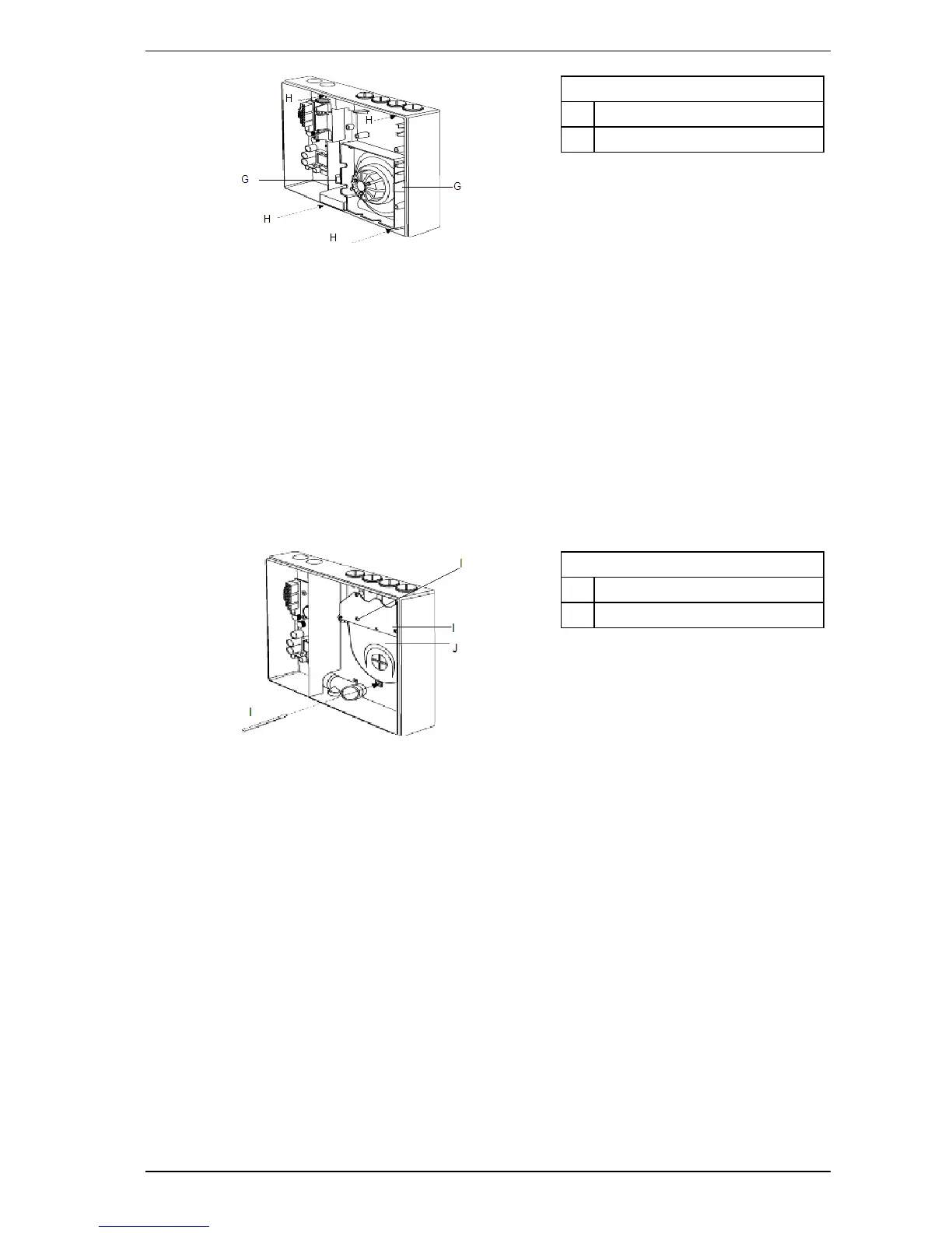
10. Unscrew the three screws holding the pipe inlet in place (I). Two screws are hidden in holes in the PCB
(Flow sensor board).
11. Lift the air inlet up and out.
Legend
I 3 Pipe-inlet retaining screws
J Pipe inlet manifold
Figure 11-4: Removing pipe inlet manifold
12. Attach the replacement manifold and chassis by reversing the procedure above.
13. Configure the VESDA VLS using Xtralis VSC by highlighting the detector in the Device Tree Window
and selecting Restore Node Configuration from the Device Menu, or reprogram the detector manually
using the LCD Programmer
Note: Power cables must be the last to be connected. Connecting the power cables before all of the data
cables can lead the unit to malfunction, requiring the VESDA VLS to be returned to the factory.

 Loading...