VESDA PipeNetwork Design Guide VESDA by Xtralis
20 www.xtralis.com
The details of the number and size of the holes to be used can be found in Table 4-1.
Legend
A Holes with same orientation
B Rubber Grommet
C Air flow
Figure 4-20: Small duct sampling - top view
For small ducts, holes are nominally spaced each 200 mm (8 in)
Table 4-1: Hole size for a small duct
Duct width No. of holes Hole Ø Nominal pipe flow
rate (L/min.) (cfm)
300 mm (12 in) 2 6 mm 15/64 in 39.0 L/min. (1.4 cfm)
500 mm (20 in) 3 5 mm 13/64 in 40.7 L/min. (1.4 cfm)
700 mm (28 in) 4 4 mm 5/32 in 35.6 L/min. (1.26 cfm)
900 mm (36 in) 5 4 mm 5/32 in 42.8 L/min. (1.51 cfm)
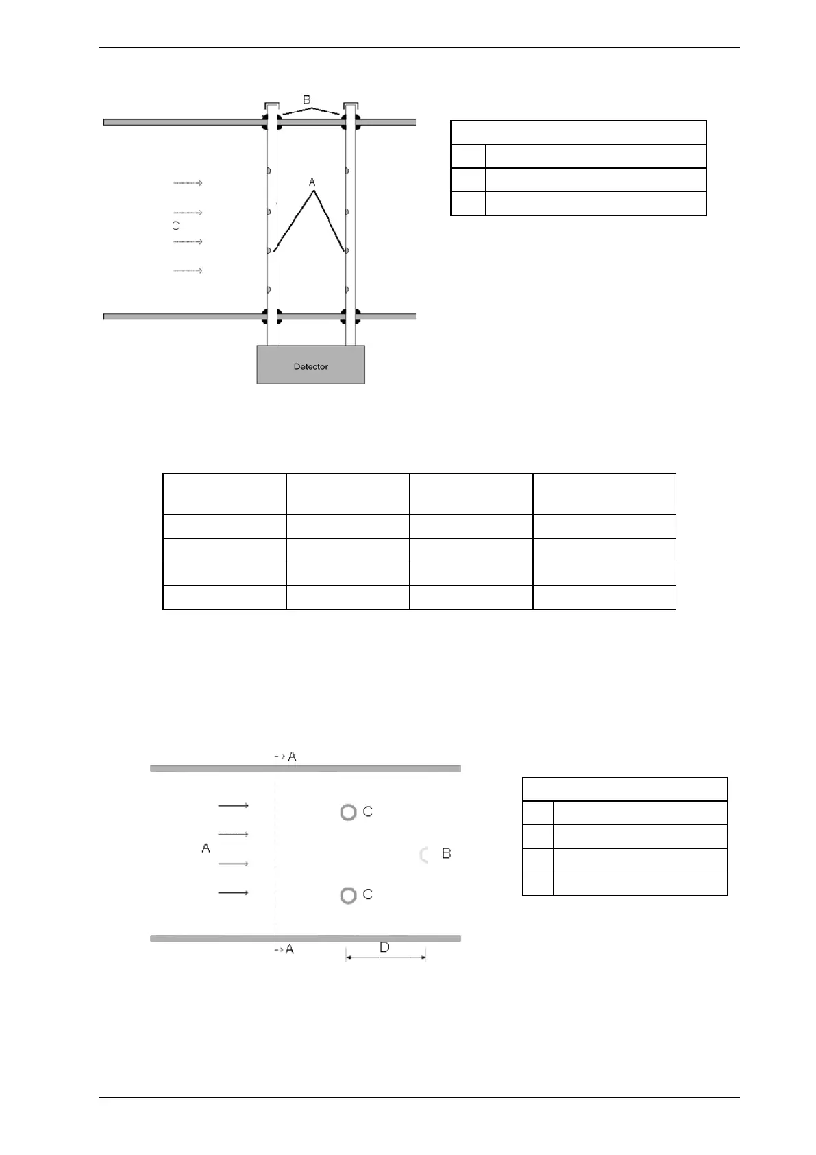
Large Ducts: Width 1 - 2 m (3 - 7 ft)
For large ducts, the inlet pipe is recommended to have two branches. Figure 4-22 shows a side view of a duct
section with the relative insertion positions for the inlet and exhaust pipes. Both inlet branches enter at a
quarter of the height of the duct from the top and bottom where H is the height of the duct.
The exhaust pipe should be inserted approximately 0.5 m (1.64 ft) further downstream in the middle of the
height of the duct.
Legend
A Duct Flow
B Exhaust pipe H/2
C Inlet pipe H/4
D 500 mm (20 in.)
Figure 4-21: Large duct sampling - side view
The diagram below shows a cross-section view of a duct with the locations of the inlet branches and exhaust
pipe. A recommendation of hole size and spacing arrangement is shown in Table 4-2.