VESDA Pipe Network Installation Guide VESDA by Xtralis
18 www.xtralis.com
11. Update the design documents with any changes that may have been made to the original plan. If the
installed system is significantly different to the original plan you may need to use ASPIRE to check
that the new design will actually work.
12. After all the tests have been completed bond the pipes together using the appropriate cement solvent.
Do not glue the pipes running into the detector manifold, as this can make it impossible to service the
detector, and will void the warranty.
13. Use appropriate labels and tag the sampling pipe, sampling holes and test points where required.
14. Update the design documents with any further changes that may have been made during the tests.
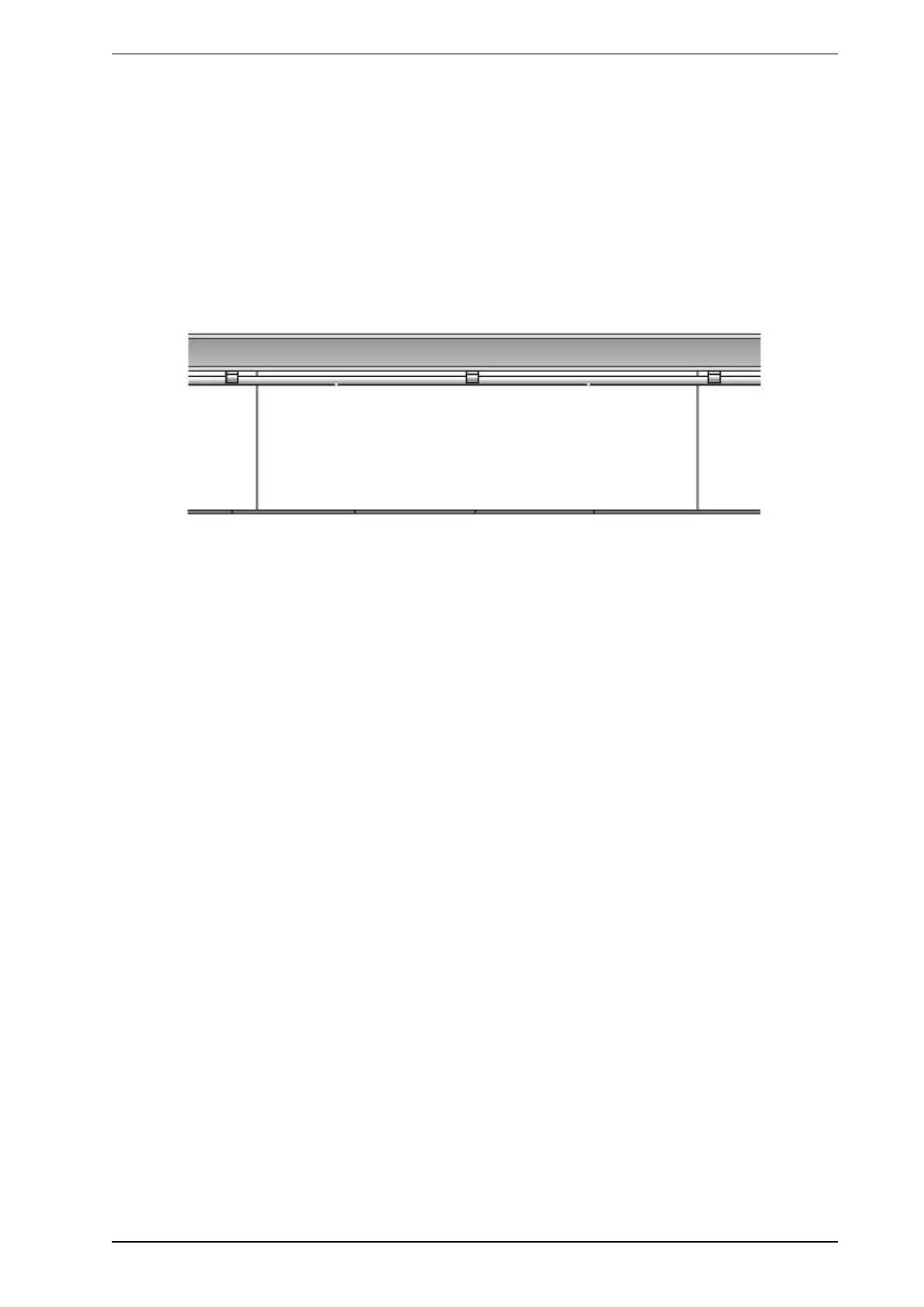
5.1.2 In-Ceiling Installation
In-Ceiling installations are pipe networks in the ceiling void between the roof of the building and the false
ceiling panels.
Figure 5-2: Typical installation in a ceiling void
1. Check the design documents to gather information on the size and configuration of the pipes. The
design documents could include pipe network design specifications, or an ASPIRE Installation Data
Pack (IDP) or a pre-engineered design.
2. Mark the spot where the detector is to be installed.
3. Identify and measure the spots for securing the pipe as required by the design documents and
guidelines for mounting pipes. Refer to Section 4.2 on page 14. Ceiling joists and/or support beams can
be used to secure the pipe.
4. Install the detector. See the detector documentation for details.
5. Secure the pipe using appropriate conduit clamps or self locking ties ensuring that the distance
between the roof and the pipe is according to the design specifications. For further information refer to
Section 3.9 on page 10.
6. When securing the pipes follow the guidelines discussed in Section 4.2 on page 13. Do not glue the
pipes at this stage. Special attention needs to be given to the expansion and contraction of pipes in
ceiling voids, as the pipes are likely to be subjected to a higher level of temperature fluctuations. In
areas of wide temperature fluctuations, it is strongly suggested that expansion Joints are used to
counter the higher rates of expansion and contraction of the sampling pipe.
7. Drill sampling holes on the underside or side of the pipe ensuring that the spacing between sampling
holes is as per the design documents and the holes are at the correct angle.
8. Check to see if the design documents requires end caps with a hole. Install as required.
9. Run the pipe to the detector.
10. Insert the pipes into the detector pipe inlet manifold. Refer to the relevant detector manual for further
information.
11. To avoid potential effects of pressure differentials it is recommended that sampled air is exhausted
from the detector back to the ceiling void.
12. Mark the design documents with any changes that may have been made during installation.
13. After all the tests have been completed bond the pipes together using the appropriate cement solvent.
Do not glue the pipes running into the detector manifold, as this can make it impossible to service the
detector, and will void the warranty.
14. Use appropriate labels and tag the sampling pipe, sampling holes and test points where required. Refer
to Section 3.11 on page 11.
15. Mark the design documents with any further changes that may have been made during the tests.