VESDA Pipe Network Installation Guide VESDA by Xtralis
24 www.xtralis.com
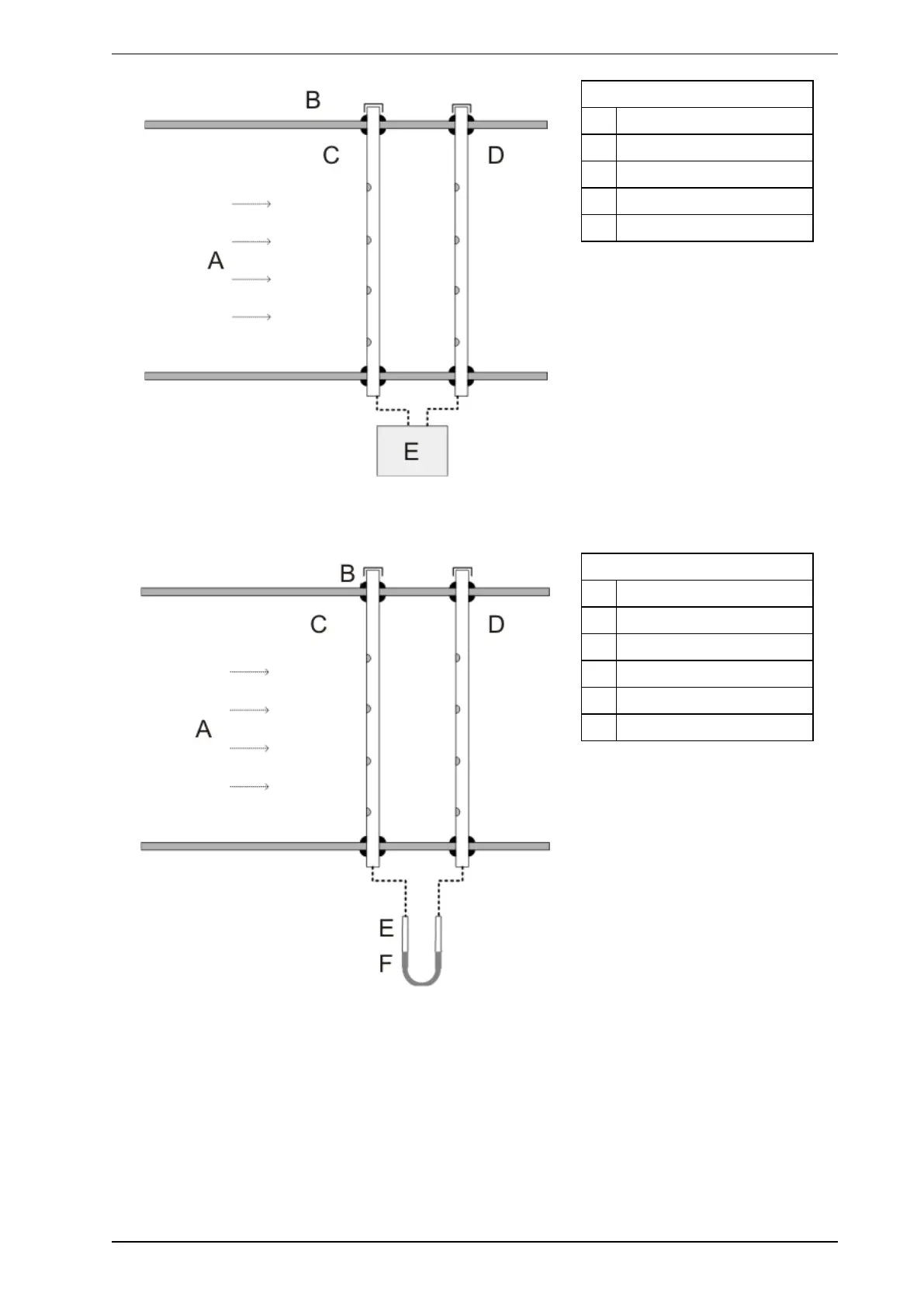
Legend
A Air flow
B Rubber grommet
C Sampling pipe
D Exhaust pipe
E Manometer pressure
Figure 5-11: Manometer testing
Connect the pipe ends to a U-shape clear flexible tube that contains water.
Legend
A Air flow
B Rubber grommet
C Sampling pipe
D Exhaust pipe
E Clear flexible tube
F Water is level
Figure 5-12: Flexible U-tube testing
Face the holes on both pipes to the airflow and slightly rotate the pipes so the water level on both sides of the
tube is the same. Mark the position of the pipes’ orientation on the pipe and the side of the duct. Connect the
detector after securing the pipe network.
Sampling probe installation:
1. Drill holes through the sides of the duct so that the intake probe can be inserted across the width of the
duct. The holes should be in the middle of the duct.
2. Drill the required number (and size) of sampling holes in the probe. Make a mark on the end of the probe
in line with the holes.