VESDA by Xtralis VESDA Pipe Network Installation Guide
www.xtralis.com 25
3. Insert the probe through the duct, and attach an end-cap without a hole in it.
4. Use the mark on the end of the probe to ensure that the holes on the probe face 20° to 45° above or
below the direction of the airflow.
5. Ensure that the holes where the intake probe enters and exits the duct are properly sealed and made air
tight.
6. Join the sampling probe to the sampling pipe network running to the detector.
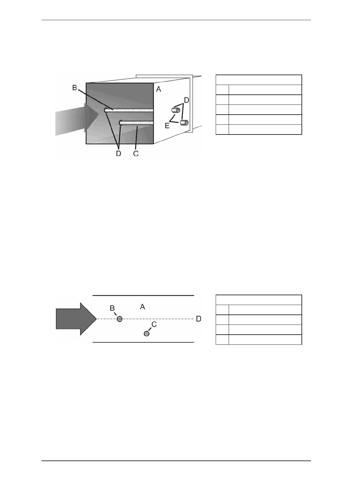
Legend
A Air duct
B Air intake probe
C Air exhaust probe
D Grommets (sealed)
E End caps without a hole
Figure 5-13: Return air duct sampling
Exhaust probe installation:
Always install the sampling probe, then install the exhaust probe.
1. On the same side of the duct that the sampling probe was inserted you will need to drill another hole for
the exhaust probe. The hole should be:
l Downwind of the sampling probe by at least 300 mm (1 ft.)
l A quarter the height of the duct up from the bottom. This is done so that the air hitting the exhaust probe
has not been disturbed by hitting the sampling probe first.
1. Drill the same number (and size) of sampling holes used in the sampling probe. Make a mark on the
end of the probe in line with the holes.
2. Attach an end-cap (without a hole), and insert the probe a third the way into the duct.
3. Use the mark on the end of the probe to ensure that the holes on the probe face 20° to 45° above or
below the direction of the airflow. These holes need to face the same direction as those used in the
sampling probe.
4. Ensure that the hole where the exhaust probe enters the duct is properly sealed and made air tight.
5. Join the exhaust probe to the exhaust pipe network running from the detector.
Legend
A Air duct
B Air intake probe
C Air exhaust probe
D Central air flow
Figure 5-14: The location of probes in duct