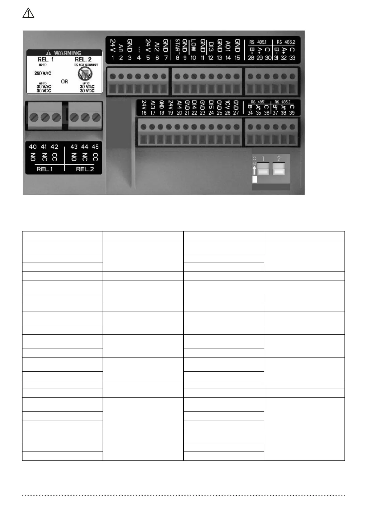
Figure 2: Auxiliary connections
Table 1:
Position number Name Description Default setting
1 Analog input 1 Power supply +24 VDC, max. 60 mA (to‐
tal, terminals 1 + 5)
Pressure sensor 1
2 Configurable analog input 1
3 Electronic GND
4 Reserved For internal use, do not connect -
5 Analog input 2 Power supply +24 VDC, max. 60 mA (to‐
tal, terminals 1 + 5)
Not selected
6 Configurable analog input 2
7 Electronic GND
8 External Start/Stop Digital start/stop input, internal pull-up
+24 VDC, contact current 6 mA
-
9 Electronic GND
10 External lack of water Low water level digital input, internal
pull-up +24 VDC, contact current 6 mA
-
11 Electronic GND
12 Digital input 3 Configurable digital input 3, internal pull-
up + 24 VDC, contact current 6 mA
Emergency start at maximum speed
13 Electronic GND
14 Analog output Configurable output Motor Speed
15 Electronic GND -
16 Analog input 3 Power supply +24 VDC, max. 60 mA (to‐
tal, terminals 16 and 19)
Not selected
17 Configurable analog input 3
18 Electronic GND
19 Analog input 4 Power supply +24 VDC, max. 60 mA (to‐
tal, terminals 16 and 19)
Not selected
20 Configurable analog input 4
21 Electronic GND
For safety and correct product usage, read the manual before this product is used.
4

 Loading...