4.8.2 I/O connections
1. Open the terminal box cover removing the screws (5). Refer to fig-
ures 2 & 3 on page 7. Use control screwdriver described under sec-
tion 4.2 to access terminal blocks.
2. Connect the appropriate wires according to the terminal block dia-
gram and the requirements of section Connection assignment on
page 9 given below in section 4.7.3.
3. Close the terminal box cover.
4.8.3 Connection assignment
• For all electrical connections, use heat resistant wires or cable that is
rated for at least 194°F (90°C). Make sure that the wiring does not
touch the motor housing, the pump, or the piping.
• Power and control wires must be run in separate channels.
• Metal conduit for power wiring must only be attached to 1/2” NPT
conduit fitting.
• For a two pump connection, wire both pumps through a communi-
cation cable connecting the 2 RS-485 ports at the pumps to termi-
nals 15, 16 & 17 for single phase pumps and 5–6 & 7 for three phase
pumps.
• Low voltage wiring is recommended to be twisted pair and shield-
ed. Sensor wiring is not to exceed 65 feet (19.8 m) in length.
NOTICE:
Cable glands are only available for low voltage wiring to protect
against cable slippage and vapor ingress into the terminal box.
5 System Description
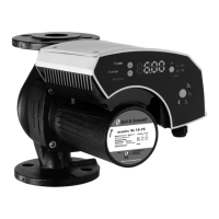
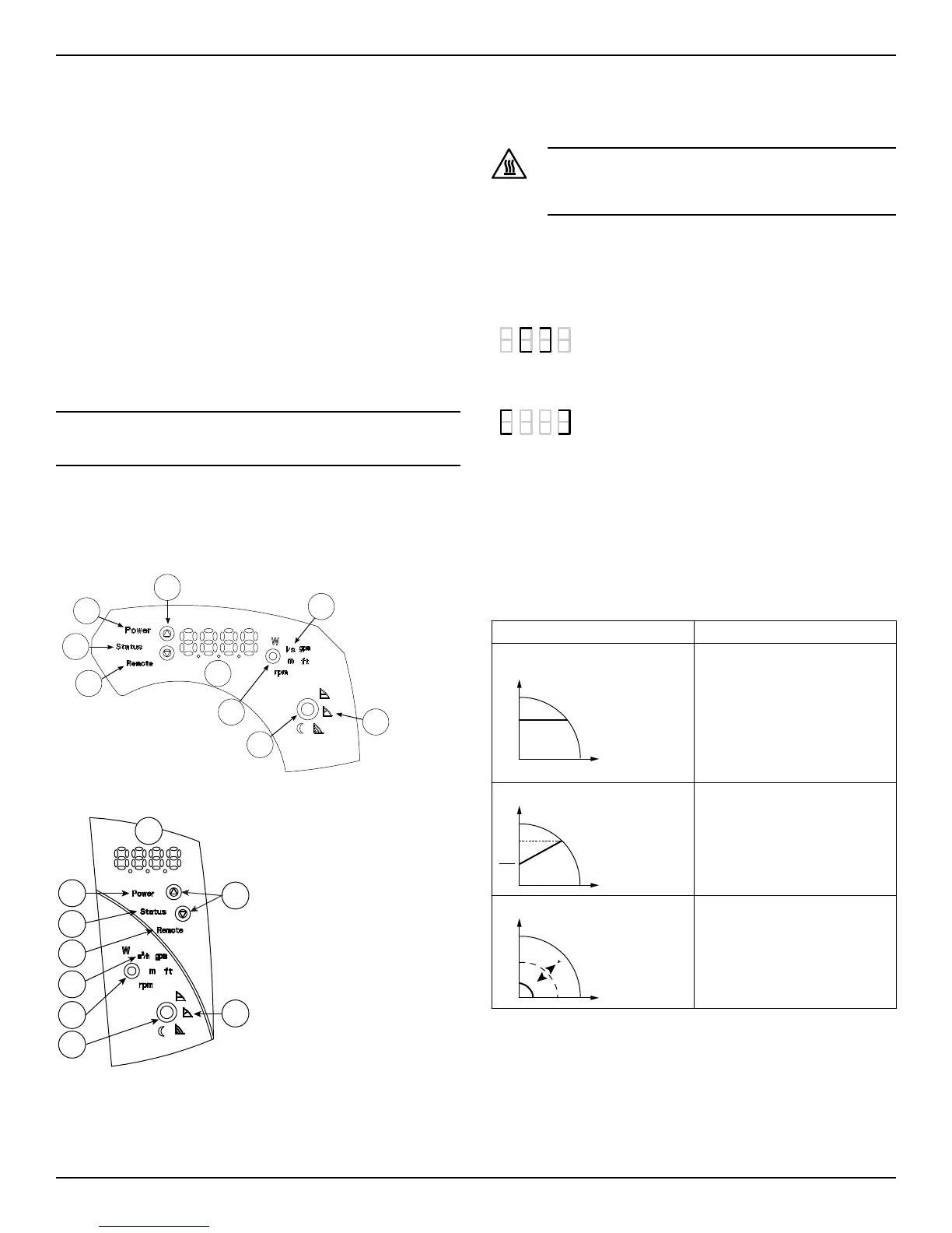
5.1 User interface
Figure 8: User interface diagram for single phase models
Figure 9: User interface diagram for three phase models
1. Control mode button
2. Control mode indicators
3. Parameter button
4. Parameter indicators
5. Setting buttons
6. Numeric display
7. Power indicator
8. Status / Fault indicator
9. Remote control indicator
Hot Surface:
Burn hazard. During normal operation, the pump surfaces
may be so hot that only the buttons should be touched to
avoid burns.
5.1.1 User interface locking/unlocking
The user interface will automatically lock if no button is pressed for ten
minutes, or if the upper setting button (5) and the parameter button (3)
are pressed for two seconds. See User interface on page 9.
If a button is pressed when the user interface is locked, the display (6)
shows:
To unlock the user interface, press the upper setting button (5) and the
parameter button (3) for two seconds. The display (6) will show:
Now it is possible to change the pump setting as required.
5.2 Functions
The main functions of the pump and control modes are selectable
through the pump user interface and the embedded I/O. Advanced
functions or communication features, can only be accessed and set via
communication bus protocol or the optional Wireless module. See the
electronic drive manual at www.bellgossett.com, for details.
5.2.1 Control Modes
Mode Description
Constant pressure
The pump maintains a constant
pressure at any flow demand. The
desired head of the pump can be
set via user interface. See Change the
set point on page 12.
Proportional pressure
The pump pressure is continuous-
ly increased/decreased depend-
ing on the increased/decreased
flow demand. The maximum head
of the pump can be set via user in-
terface. See Change the set point on
page 12.
Fixed speed control
The pump maintains a fixed speed
at any flow demand. The speed of
the pump can be set via user inter-
face. See Change the set point on page
12.
All the above control modes can be combined with the night mode
function.
5 System Description
ecocirc
®
XL INSTRUCTION MANUAL 9