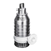
1.
Outlet line
2.
Inlet line
3.
Line to drain
4.
Air vent
Figure 23: T-installation (generic pump shown)
1.
Inlet line
2.
Outlet line
3.
Line to drain
Figure 24: Z-installation (generic pump shown)
2. Drain the pump by opening the valve on the drain line.
3. Remove the pump from the installation.
6.5.4.2 Remove the Adaptive N
™
impeller: P, S, T, Z installations
To see which pumps are Adaptive N
™
, see Product Description on page 11.
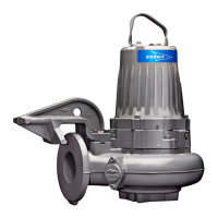
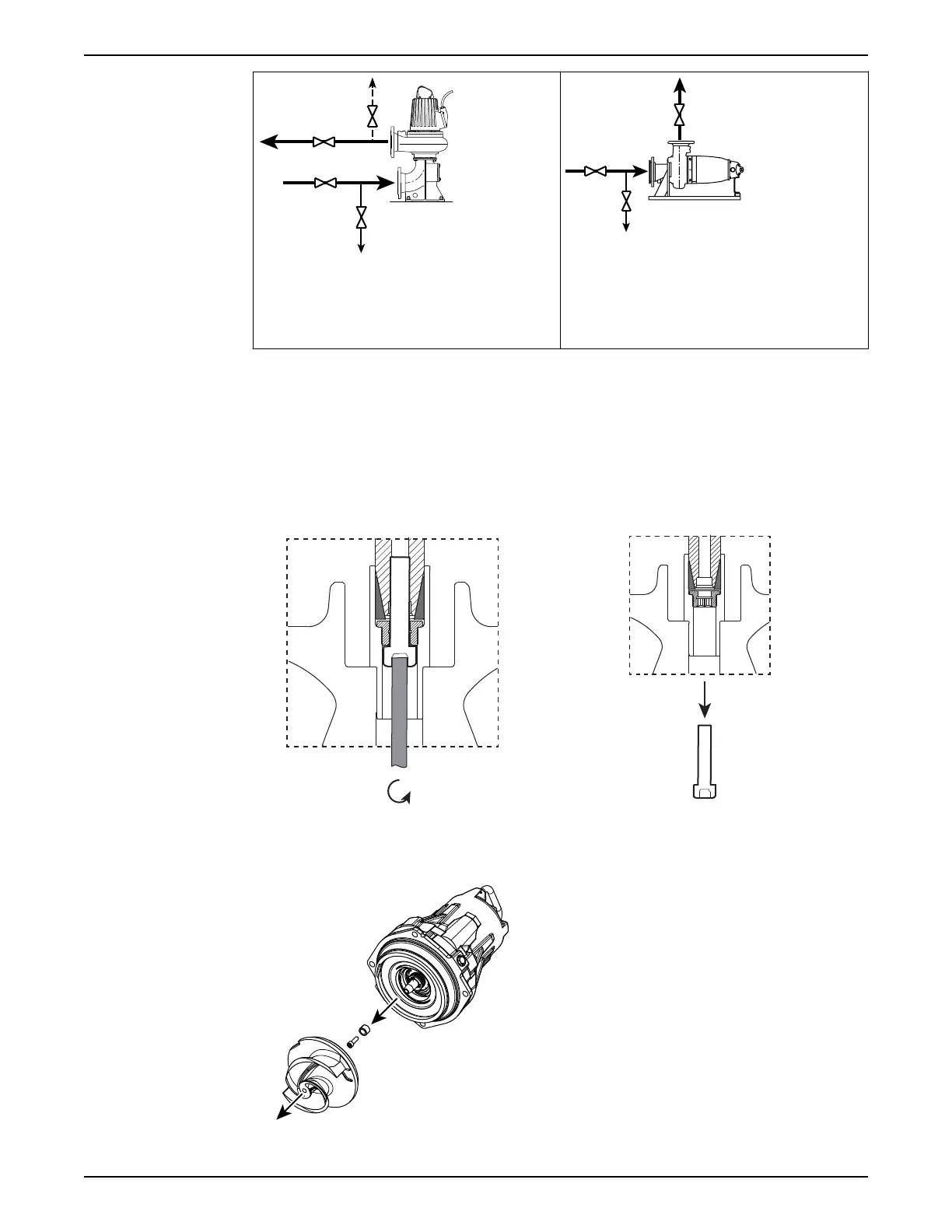
1. Remove the pump housing.
2. Remove the impeller.
a) Loosen the impeller screw.
b) Remove the impeller.
Use the impeller puller or the crowbars.
c) Remove the impeller screw and the conical sleeve.
6 Maintenance
62 Flygt 3102 Installation, Operation, and Maintenance Manual
 Loading...