Do you have a question about the Xylem OMNI sensus C2 and is the answer not in the manual?
Details the OMNI+ register features, including programmable totalizer, digital pulse, AMR reading, and test totalizer.
Explains OMNI+ alarms for conditions like reverse flow, leak, high flow, and low battery.
Describes OMNI+ data logging capabilities, storing 180 days of hourly data.
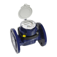
Presents technical specifications for OMNI meters, covering input power, output signal, and wiring.
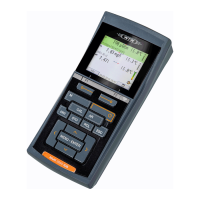
Describes the Segment Test view for checking LCD icon functionality and display accuracy.
Explains the Totalizer view, displaying consumption values, units, and active notification icons.
Details the LCD flow direction indicator showing positive, negative, or no flow.
Covers the Notification view for alarms and events, showing up to six active events.
Explains the OMNI+ modes: Smart Mode for AMR/customer ID/alarms, Normal Mode for ID/AMR.
Describes Bell and Flag icons on the LCD indicating active or recent events/alarms.
Explains the battery icon indicating low battery or need for replacement.
Details retrieving data via NFC interface when the battery fails.
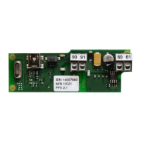
Details electrical connection options for OMNI+ registers and wiring configurations.
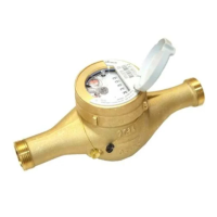
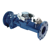
Lists the necessary tools for OMNI meter installation, including specific bolt sizes.
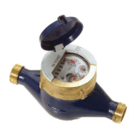
Covers factors for valid registration, performance, and longevity during installation.
Lists tools needed for measuring chamber removal and disassembly, including hex drivers and wrenches.
Step-by-step guide to removing the measuring chamber from the meter body.
Instructions for disassembling the measuring chamber for part replacement.
Details on replacing the measuring insert, including O-ring lubrication and alignment.
Provides torque specifications for various OMNI meter types and components.
Guides on powering on, positioning CommandLink, and activating SmartPoint modules.
Describes common errors encountered with FieldLogic Tools and suggests corrective actions.
Details activation errors and their causes, such as communication failure or GPS issues.
Table listing common activation errors, their possible causes, and corrective actions.
Addresses issues with detecting or communicating with the SmartPoint module via FieldLogic.
Table listing common communication errors, possible causes, and corrective actions.
Lists other potential errors like storage issues, utility code mismatch, and timeouts.
Steps to enable an unused port on a dual port SmartPoint module using FieldLogic Tools.
Instructions for modifying configuration parameters of a two-way SmartPoint module.
Procedure for retrieving interval data from a two-way SmartPoint module using FieldLogic Tools.
Guides on viewing SmartPoint module status, configuration, and network settings.
Steps to deactivate an activated two-way SmartPoint module using FieldLogic Tools.
| Manufacturer | Xylem |
|---|---|
| Parameter | Flow |
| Measurement Principle | Electromagnetic |
| Accuracy | ±0.5% of reading |
| Outputs | 4-20 mA, pulse, frequency |
| Operating Temperature | -20°C to +60°C |
| Process Connections | Flanged |