EasyManua.ls Logo

Xylem SENSUS PolluTherm Integrator - User Manual

Xylem SENSUS PolluTherm Integrator
14 pages
Print Icon
To Next Page IconTo Next Page
Loading...
Heat / Cooling meter integrator PolluTherm
Installation and operation instructions
M H 6111 INT PolluTherm, page 1
The integrator PolluTherm is used for energy
consumption measurement in heating or cooling
systems filled with the energy carrier liquid water.
PolluTherm may also be used with water
containing antifreeze using a programmed
correction factor. In this case the PolluTherm is
not officially metrologically calibrated. These
installation and operation instructions specify how
to install and operate the integrator PolluTherm.
They are an essential part of the supplied items
and shall be handed over to the final user.
Content
Supplied items ..................................................... 1
1. Technical data ................................................. 1
2. Safety instructions ........................................... 2
3. Required tools .................................................. 2
4. Combination of the sub-units ........................... 2
4.1 Programming the input pulse value ............ 2
5. Installation of the sub-units .............................. 3
5.1 Flow sensor ................................................ 3
5.3 Mounting of the integrator ........................... 4
6. Connection of the sub-units ............................. 4
6.1 Connection of the flow sensor .................... 5
6.2 Connection of the temperature sensors ...... 5
7. Exchange of the integrator module .................. 5
8. Display options ................................................ 6
8.1 User menu (example) ................................. 6
8.2 Target day menu (example) ....................... 7
8.3 Archive menu (example)............................. 7
8.4. Service menu (example) ............................ 8
8.5 Control menu for tariff purposes (example) 9
8.6 Parameter menu (example) ........................ 9
9. Functional test, sealing .................................. 10
10. Potential error situations .............................. 10
11. Data interface and options ........................... 10
11.1 Optical interface ..................................... 10
11.2 M-Bus-plug-in unit acc. to EN 13757-3 ... 10
11.3 Remote reading plug-in unit ................... 11
11.4 M-Bus plug-in unit with two contact inputs
....................................................................... 11
11.5 USB plug-in unit (for M-Bus slot) ............ 11
11.6 LONWORKS
®
-FTT10A (for M-Bus slot) . 11
11.7 Inserting the plug-in unit into the heat
meter .............................................................. 11
11.8 Combined heating/cooling meter (ordering
option) ............................................................ 11
11.9 Optional integrated data logger (ordering
option) ............................................................ 12
11.10 Retrofitting from battery unit to power
supply unit ...................................................... 12
12. Information on the extension of temperature
sensor cables ................................ ..................... 12
Annex 1: Declaration of conformity acc. directive
2004/22EC (MID) ............................................... 14
Supplied items
Integrator PolluTherm (incl. temperature
sensors and immersion sleeves, where
appropriate)
Sealing material (self-lock seals, sealing
wire), cable binders for strain relief
Fastening material (2 screws,
2 dowels, C-rail)
These installation and operating instructions
1. Technical data
Integrator
Temperature measuring
range
= 1 … 180 °C
Temperature difference
range
= 3 … 150 K
Switch-off threshold 0,15 K
Measuring accuracy
Better than (%):
+ (0,5 +
min
/ )
Updating time and
integration cycles resp.:
- Temperatures
- Flow rate, power
- Energy, volume
2 sec
4 sec
4 sec (16 sec *)
* in case of battery supply
Optical data interface
Physical acc. to EN 61107
Data record acc. to EN 13757-3
Suitable temperature
sensors
Pt 500
Connection in two- or four-wire
technology
Power supply
(certification period of the
meter may be defined by
national laws)
Battery for 6 years
(optional: 11 years)
or mains supply 230 V AC or
24 V AC
Electromagnetic
environment condition
Class E 1
Mechanical environment
condition
Class M 2
Protection class IP 54
Ambient temperature 5 … 55 °C
Storing temperature -20 … +65 °C
Relative air humidity < 93 %
Size (H x B x T)
in terms of wall mounting
ca. 159 x 125 x 52 mm
Pulse input value
in l
0,25
or
1
2,5
or
10
25
or
100
250,
1.000 or
10.000
Display of the
integrator with
decimal digits for
m³, MWh or GJ
00000,000 000000,00 0000000,0 00000000
Pulse value in case
of remote heat
quantity reading in
MWh or GJ
0,001 0,01 0,1 1
Pulse value in case
of remote volume
reading in l
1 10 100 1.000
Question and Answer IconNeed help?

Do you have a question about the Xylem SENSUS PolluTherm Integrator and is the answer not in the manual?

Summary

Supplied Items

Technical Data

Safety Instructions

Required Tools

Combination of Sub-units

Programming the Input Pulse Value

Procedure for setting the input pulse value once for the integrator. Attention is required due to calibration regulations.

Installation of Sub-units

Flow Sensor

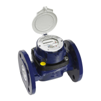
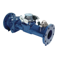
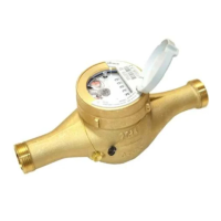
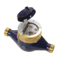
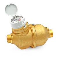
Details on installing the flow sensor in heating and cooling systems, including pipe orientation and types.

Installation of Temperature Sensors

Guidance on installing Pt 500 temperature sensors, including optimal angles and immersion depth based on pipe size.

Mounting of the Integrator

Instructions for attaching the integrator housing to a C-rail using screws and snap hooks for secure mounting.

Connection of Sub-units

Connection of the Flow Sensor

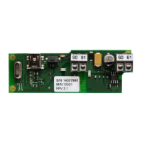
Procedure for connecting the pulse cable of the flow sensor to terminals 10 (+) and 11 (-), noting polarity for Reed contacts.

Connection of the Temperature Sensors

Details on connecting Pt 500 temperature sensors using two-wire or four-wire technology, specifying terminals and cable requirements.

Exchange of Integrator Module

Display Options

User Menu (Example)

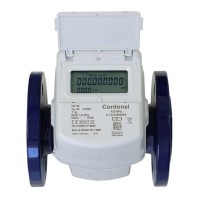
Illustrates the user menu display, showing error messages, energy consumption, target consumption, and volume readings.

Target Day Menu (Example)

Shows example displays for the target day menu, including heat/cooling energy, volume, and tariff consumption values.

Archive Menu (Example)

Details the archive menu, displaying historical data like energy consumption, volume, and tariff values for past months.

Service Menu (Example)

Provides examples of the service menu, showing maximum values, meter settings, date, time, and firmware version.

Control Menu for Tariff Purposes (Example)

Parameter Menu (Example)

Functional Test and Sealing

Potential Error Situations

Data Interface and Options

Optical Interface

Describes the standard optical data interface for changing settings and reading out the meter using software like MiniCom.

M-Bus Plug-in Unit acc. to EN 13757-3

Details the M-Bus plug-in unit for meter readout via M-Bus level converter, including primary and secondary addresses.

Remote Reading Plug-in Unit

Explains remote reading plug-in units for outputting heat quantity and volume pulses, used for mains or battery-operated devices.

M-Bus Plug-in Unit with Two Contact Inputs

Details the M-Bus plug-in unit for connecting external consumption meters with passive remote reading contacts.

USB Plug-in Unit (for M-Bus Slot)

Describes the USB plug-in unit for connecting the integrator to a PC/Notebook via USB, requiring a software driver.

LONWORKS-FTT10 A (for M-Bus Slot)

Explains the LONWORKS plug-in module for integrating the meter into a building automation system via LONTALK protocol.

Inserting Plug-in Unit into Heat Meter

Combined Heating;Cooling Meter (Ordering Option)

Optional Integrated Data Logger (Ordering Option)

Retrofitting from Battery Unit to Power Supply Unit

Information on Extending Temperature Sensor Cables

Annex 1: Declaration of Conformity acc. Directive 2004;22 EC (MID)

Overview

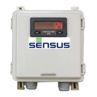
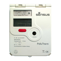
The Sensus PolluTherm is an integrator designed for measuring energy consumption in heating and cooling systems that use liquid water as the energy carrier. It can also be used with water containing antifreeze, provided a programmed correction factor is applied, though in this case, it is not officially metrologically calibrated. This device is an essential component of a comprehensive energy measurement system.

Function Description

The PolluTherm integrator calculates energy consumption based on inputs from a flow sensor and a pair of temperature sensors (Pt 500). It can function as both a heat meter and a cooling meter, with an optional "PolluTherm H" or "PolluTherm X H" version for combined heating/cooling applications. The device continuously monitors temperatures and flow rates, integrating these values over time to determine accumulated energy and volume.

For heating systems, the flow sensor is typically installed in the colder return pipe. If installed in the warmer supply pipe, the PolluTherm X version is required. In cooling systems, it is recommended to install the flow sensor in the warmer return pipe, also requiring the PolluTherm X version. The device supports various flow sensor types (AN 130, MeiStream FS, Woltman WPD FS) with specific temperature ranges.

The integrator features a comprehensive display system, organized into six menus: User, Target Day, Archive, Service, Control for Tariff Purposes, and Parameter. These menus allow users to view current and historical consumption data, maximum values, meter settings, and error messages.

Important Technical Specifications

  • Temperature Measuring Range: 1 to 180 °C
  • Temperature Difference Range: 3 to 150 K
  • Switch-off Threshold: 0.15 K
  • Measuring Accuracy: Better than (0.5 + Amin / ΔΘ) %
  • Updating Time & Integration Cycles:
    • Temperatures: 2 sec
    • Flow rate, power: 4 sec
    • Energy, volume: 4 sec (16 sec with battery supply)
  • Optical Data Interface: Physical acc. to EN 61107, Data record acc. to EN 13757-3
  • Suitable Temperature Sensors: Pt 500, connected in two- or four-wire technology
  • Power Supply: Battery for 6 years (optional: 11 years) or mains supply 230 V AC / 24 V AC
  • Electromagnetic Environment: Class E 1
  • Mechanical Environment: Class M 2
  • Protection Class: IP 54
  • Ambient Temperature: 5 to 55 °C
  • Storing Temperature: -20 to +65 °C
  • Relative Air Humidity: < 93%
  • Size (H x B x T) in terms of wall mounting: ca. 159 x 125 x 52 mm
  • Pulse Input Values (in litres): 0.25, 1, 2.5, 10, 25, 100, 250, 1,000, 10,000 (programmable once)
  • Display with Decimal Digits: 00000,000 (m³, MWh, GJ)
  • Pulse Value for Remote Heat Quantity Reading: 0.001, 0.01, 0.1, 1 (MWh or GJ)
  • Pulse Value for Remote Volume Reading: 1, 10, 100, 1,000 (litres)
  • Mains-operated devices: Voltage 220-240 V AC or 24 V AC, 50/60 Hz, Max. power consumption 0.5 VA, Cable length ca. 1.1 m. Fused at 6 A protection.

Usage Features

  • Flexible Installation: The flow sensor can be installed in either the supply or return pipe, depending on the system type (heating or cooling) and PolluTherm version. Temperature sensors are installed at specific angles (45° for < DN 50, vertically for > DN 100) and immersion depths to ensure accurate readings.
  • User-Friendly Display: The device features an LC display with a red key for navigation. Short presses activate display items within a menu, while holding the key for 2 seconds accesses different menus. A flashing vane symbol indicates incoming volume pulses.
  • Programmable Input Pulse Value: For devices not pre-programmed at the factory, the input pulse value can be set once via the display, by pressing the red key and removing a bridge in the terminal block.
  • Data Interfaces and Options:
    • Optical Interface: Standard on all meters, allowing data readout and settings changes via programming software (MiniCom) and optical data couplers (RS 232 or USB).
    • M-Bus Plug-in Unit (EN 13757-3): Enables meter readout via primary or secondary address with an M-Bus level converter (300 and 2400 baud).
    • Remote Reading Plug-in Unit (FZS/N or FZS/B): Provides heat quantity and volume pulses output for mains-operated or battery-operated devices, respectively.
    • M-Bus Plug-in Unit with Two Contact Inputs: Allows connection of two external consumption meters (cold water, warm water, electricity, gas) with passive remote reading contacts.
    • USB Plug-in Unit: Connects the integrator to a PC/Notebook/Handheld Computer via USB.
    • LONWORKS®-FTT10A: Integrates the meter into a building automation system via LONTALK protocol.
  • Combined Heating/Cooling Meter (Ordering Option): Automatically switches between metering heating and cooling energy based on supply flow temperature and temperature difference.
  • Optional Integrated Data Logger: Stores consumption and instantaneous values (power, flow rate, temperatures) at selectable time intervals, readable via optical interface, M-Bus, or Mini-Bus.

Maintenance Features

  • Module Exchange: After the certification or operating life expires, only the calibrated integrator module needs to be exchanged within the casing. This involves opening the lid, removing a fastening screw, and carefully pulling out the module.
  • Battery Replacement: For mains-operated units supplied until September 2010, the power supply must also be replaced when exchanging the module due to a voltage change. For battery-operated units, the main battery (D) can be replaced, and a backup battery (AA 3.6V) is used for date and short-term emergency power.
  • Self-Checking Function: The PolluTherm is equipped with an automatic self-checking function that displays four-figure error codes (Err XYZO) in case of system anomalies, aiding in troubleshooting.
  • Sealing: To prevent manipulation, the meter must be sealed at specific points: flow sensor screw connections, temperature sensor installation points, and the integrator lid.
  • Cable Extension: Temperature sensor cables can be extended by up to 23 meters using four-wire technology (e.g., I-Y(St)Y 2x2x0.8, minimum core size 0.5 mm²) and a junction box. This ensures that cable resistance does not affect measurement accuracy.
  • Power Failure Backup: Mains-operated PolluTherm units with a backup battery can maintain measuring and counting operations for up to 90 days during a power interruption. After 90 days, the backup battery secures the main memory, date, and time.

Xylem SENSUS PolluTherm Integrator Specifications

General IconGeneral
BrandXylem
ModelSENSUS PolluTherm Integrator
CategoryMeasuring Instruments
LanguageEnglish

Related product manuals