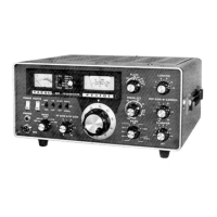
Do you have a question about the Yaesu FT-101E and is the answer not in the manual?
Selects between internal VFO, external VFO, or crystal oscillator.
Selects the operating mode: LSB, USB, AM, CW, or TUNE.
Controls receiver RF gain and audio output level.
Used to tune the operating frequency with the band switch.
Selects the desired amateur radio band for operation.
Allows fine-tuning of receiver frequency for clear reception.
Tunes signal circuits for optimal transmit and receive performance.
Adjusts microphone gain and transmitter carrier level.
Tunes the final amplifier's plate circuit.
Tunes the output circuit for antenna impedance matching.
Controls the output level of the RF processor.
Main switch to turn the transceiver ON/OFF.
Controls power to transmitter tube heaters for warm-up.
Selects transmitter mode: manual, push-to-talk, or voice-activated.
Engages the RF speech processor to improve intelligibility.
Eliminates noise pulses caused by ignition or other interference.
Reduces incoming signal strength to prevent overload.
Provides frequency markers for calibration.
Jack for connecting headphones for private listening.
Microphone input jack for voice transmission.
Selects meter display for PA current, power output, or ALC.
Audio input for auxiliary station equipment.
IF signal output for external equipment like panoramic adapters.
Audio output for an external speaker.
Jack for external transmit control, like a foot switch.
Speech input terminal for phone patch connections.
Receiver output connection for phone patch or other use.
Sidetone output for additional receivers.
Anti-trip input from an additional receiver.
Power outlet for an optional cooling fan.
Adjustment for relative power output meter indication.
RF signal output for external equipment like transverters.
Ground connection point.
Protects RF amplifier transistor from strong signals.
Connection for an external receiver antenna.
Coaxial connection for the main antenna.
Accessory socket for operating voltages and relays.
Key jack for CW code operation.
Connection point for an external VFO.
Fuse holder for various fuses.
Power receptacle for AC and DC cables.
Steps to perform before connecting power to ensure unit integrity.
Guide on using the main tuning dial and band selector.
Steps to calibrate the receiver for optimal performance.
Initial steps to prepare the transmitter for final tuning.
Detailed steps to achieve maximum transmitter output.
How to use the RF speech processor for clearer voice transmission.
Lists all vacuum tubes and semiconductor devices used in the unit.
Description of the IF unit's circuitry and function.
Description of the high-frequency IF unit's circuitry.
Description of the low-frequency IF unit's circuitry.
Description of the audio unit, including microphone and speaker circuits.
Description of the modulator unit for SSB and AM signals.
Description of the unit that regulates DC power supply voltages.
Description of the Variable Frequency Oscillator unit.
Description of the noise blanker circuit for reducing interference.
Description of the unit for crystal control and RF processing.
Details on using crystal-controlled operation.
Explains the function and adjustment of the RF processor.
Description of the rectifier unit providing DC voltages.
Overview of the main chassis containing core components.
Details the AC and DC power supply system.
Explains the preselect tuning controls.
Description of the final amplifier stage.
Explanation of the transceiver's metering functions.
Instructions for installing an optional CW filter.
Lists the necessary test equipment for alignment procedures.
General guidelines and precautions for performing alignment.
Procedure to adjust the S-meter for accurate signal strength readings.
How to adjust the noise blanker threshold for effective noise reduction.
Steps to adjust the Voice Operated Transmit (VOX) controls.
Adjusting the volume of the CW sidetone audio.
Procedure to balance the carrier for proper SSB operation.
Adjusting the Automatic Level Control meter reading.
Adjusting the RF speech processor for improved intelligibility.
Adjusting the voltage regulator to provide stable DC output.
Fine-tuning the clarifier control for frequency alignment.
Setting the bias for the final amplifier tubes for linearity.
Adjusting the meter to indicate relative power output.
Procedure to neutralize the final amplifier tubes.
Component details for the RF unit's main PCB.
Component details for the IF unit module.
Component details for the mixer unit module.
Component details for the low-frequency IF unit's PCB.
Component details for the Fix/RF Process unit.
Component details for the Noise Blanker unit.
Component details for the VFO unit.
Component details for the Rectifier unit.
Component details for the main chassis.
| Brand | Yaesu |
|---|---|
| Model | FT-101E |
| Category | Transceiver |
| Language | English |